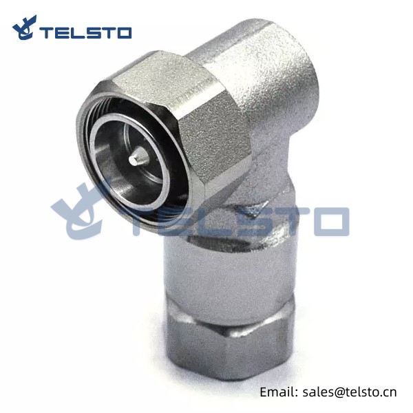
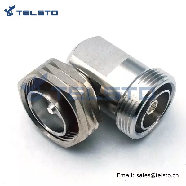
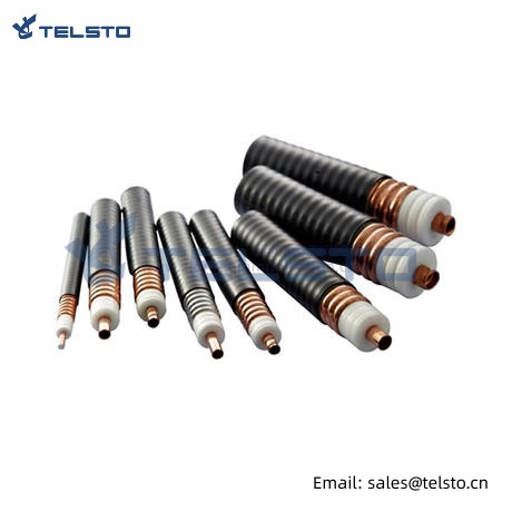
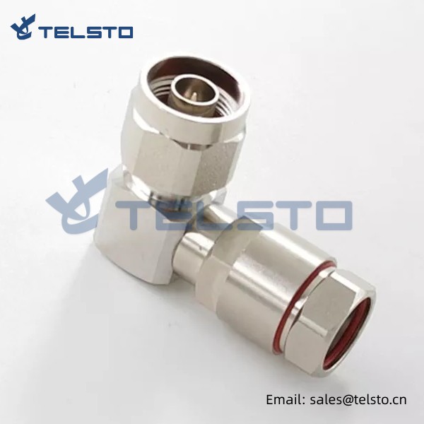
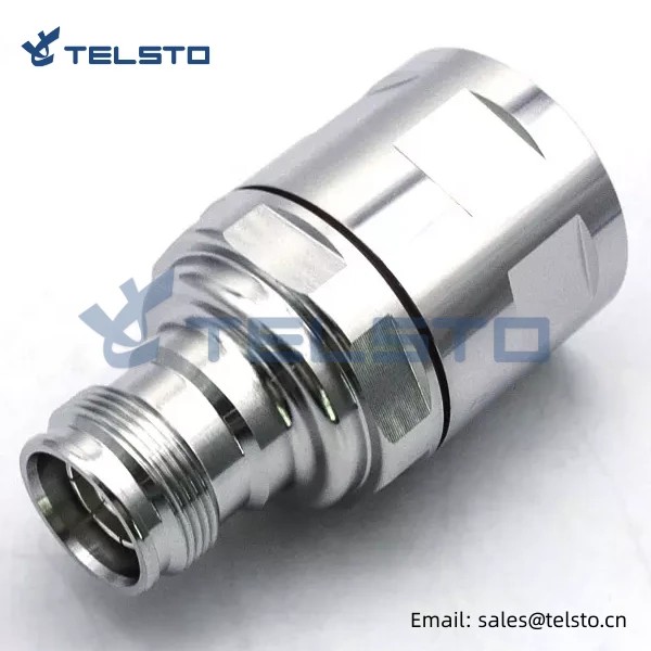
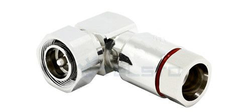
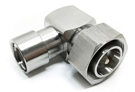
RF Connector 4.3-10 Mini DIN Male Right Angle For 1/2 Feeder Cable
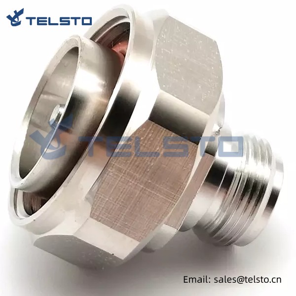
4.3-10 series is designed to meet the rising performance needs of mobile network equipment e.g. to connect the RRU to the antenna. The small size and low weight of these connectors do justice to the miniaturization of mobile radio network components. Three different coupling mechanisms of the plug connectors screw, quick-lock/push-pull and hand-screw types are mate able with all jack connectors.
| Interface | |||
| According to | IEC 60169-54 | ||
| Electrical | |||
| Characteristic Impedance | 50 ohm | ||
| Frequency Range | DC-6GHz | ||
| VSWR | VSWR≤1.10(3.0G) | ||
| PIM3 | ≤-160dBc@2x20w | ||
| Dielectric Withstanding Voltage | ≥2500V RMS,50hz,at sea level | ||
| Contact Resistance | Center Contact ≤1.0mΩ Outer Contact ≤1.0mΩ | ||
| Dielectric Resistance | ≥5000MΩ | ||
| Mechanical | |||
| Durability | Mating cycles ≥500cycles | ||
| Material and plating |
|||
|
Material |
plating | ||
| Body | Brass | Tri-Alloy | |
| Insulator | PTFE | - | |
| Center conductor | Tin Phosphor bronze | Ag | |
| Gasket | SIlicone rubber | - | |
| Other | Brass | Ni | |
| Environmental | |||
| Temperature Range | -40℃~+85℃ | ||
| Rosh-compliance | Full ROHS compliance | ||
1. These characteristics are typical but may not apply to all connectors.
2. OEM and ODM are available.
| 4.3-10 Male/Female connector for 1/2" flexible RF cable | TEL-4310M/F.12-RFC |
| 4.3-10 Male/Female connector for 1/2" Super flexible RF cable | TEL-4310M/F.12S-RFC |
| 4.3-10 Male/Female Right Angle connector for 1/2" flexible RF cable | TEL-4310M/FA.12-RFC |
| 4.3-10 Male/Female Right Angle connector for 1/2" Super flexible RF cable | TEL-4310M/FA.12S-RFC |
| 4.3-10 Male/Female connector for 3/8" Super flexible RF cable | TEL-4310M/F.38S-RFC |
| 4.1-9.5 Mini DIN Male connector for 3/8" superflex cable | TEL-4195-3/8S-RFC |
| 4.3-10 Male/Female connector for 7/8" flexible RF cable | TEL-4310M/F.78-RFC |
| 4.3-10 Male connector for 1/4" Superflexible Cable | TEL-4310M.14S-RFC |
| 4.3-10 Male connector for LMR400 cable | TEL-4310M.LMR400-RFC |
Related
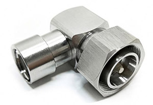
Model: TEL-4310MA.12-RFC
Description:
4.3-10 Male Right Angle connector for 1/2″ flexible cable
| Material and Plating | |
| Center contact | Brass / Silver Plating |
| Insulator | PTFE |
| Body & Outer Conductor | Brass / alloy plated with tri-alloy |
| Gasket | Silicon Rubber |
| Electrical Characteristics | |
| Characteristics Impedance | 50 Ohm |
| Frequency Range | DC~3 GHz |
| Insulation Resistance | ≥5000MΩ |
| Dielectric Strength | ≥2500 V rms |
| Center contact resistance | ≤1.0 mΩ |
| Outer contact resistance | ≤1.0 mΩ |
| Insertion Loss | ≤0.1dB@3GHz |
| VSWR | ≤1.1@-3.0GHz |
| Temperature range | -40~85℃ |
| PIM dBc(2×20W) | ≤-160 dBc(2×20W) |
| Waterproof | IP67 |
Shanghai Qikun Communication Technology Co., Ltd. takes customer first and service first as its corporate culture, adheres to the business philosophy of integrity, professionalism, innovation and cooperation, and is committed to providing customers with high-quality, efficient and value-added communication technology services. Here are some advantages of our company:
We focus on customer experience and constantly improve service quality. We take customer needs as the starting point, provide customized solutions for customers through effective communication and cooperation, and strictly control service quality to ensure maximum customer satisfaction.
We have a high-quality team, strong technical force, rich practical experience and innovative spirit. Adhering to the concept of “professional achievement in the future”, we continue to learn and expand the technical field and provide customers with the latest, best and most professional services
Installation Instructions of N or 7 / 16 or 4310 1 / 2″ super flexible cable
Structure of connector: ( Fig1 )
A. front nut
B. back nut
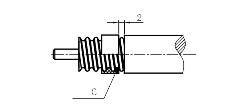
C. gasket
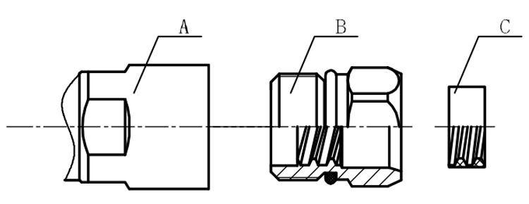
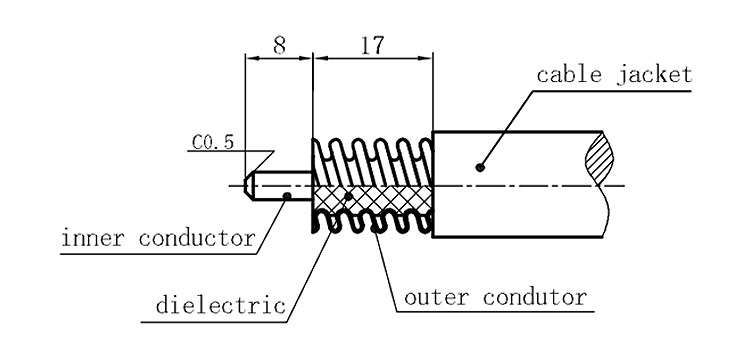
Stripping dimensions is as shown by diagram ( Fig2 ), attention should be paid while stripping:
1. The end surface of inner conductor should be chamfered.
2. Remove impurities such as copper scale and burr on the end surface of the cable.
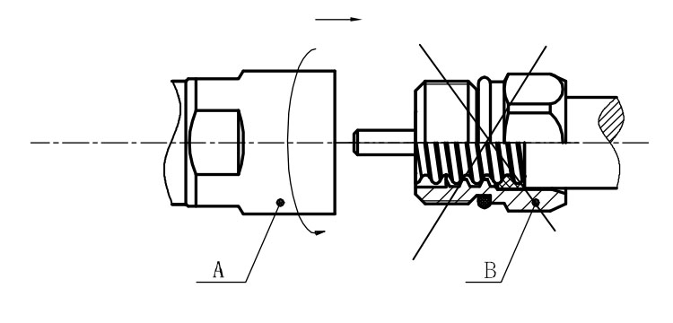
Assembling the sealing part: Screw the sealing part in along the outer conductor of the cable as shown by the diagram ( Fig3).
Assembling the back nut (Fig3).
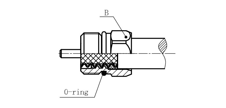
Combine the front and back nut by screwing as shown by diagram ( Figs( 5)
1. Before screwing, smear a layer of lubricating grease on the o-ring.
2. Keep the back nut and the cable motionless, Screw on main shell body on back shell body. Screw down main shell body of back shell body using monkey wrench. Assembling is finished.
