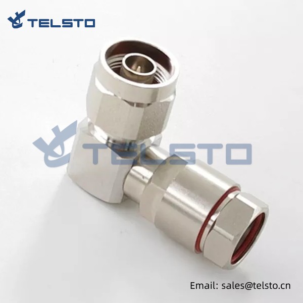
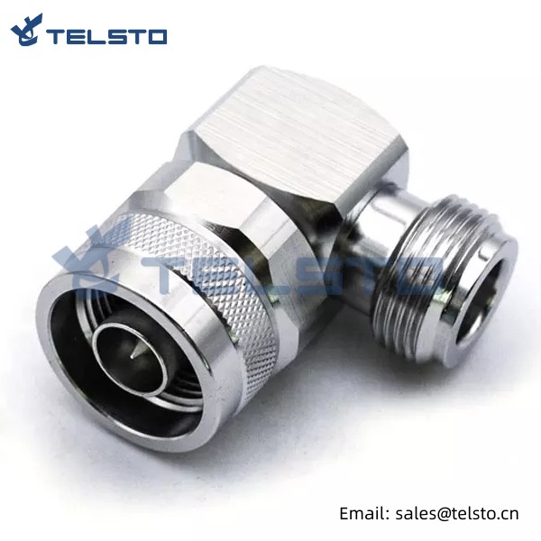
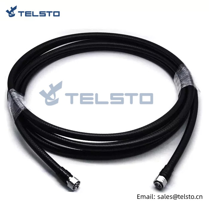
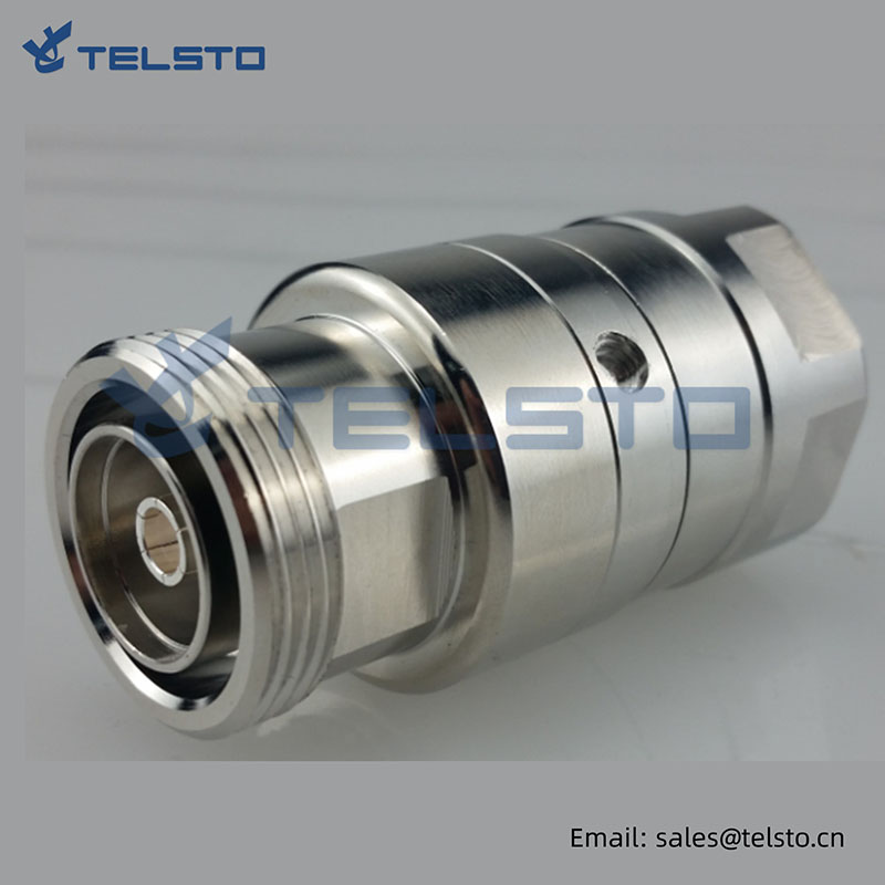
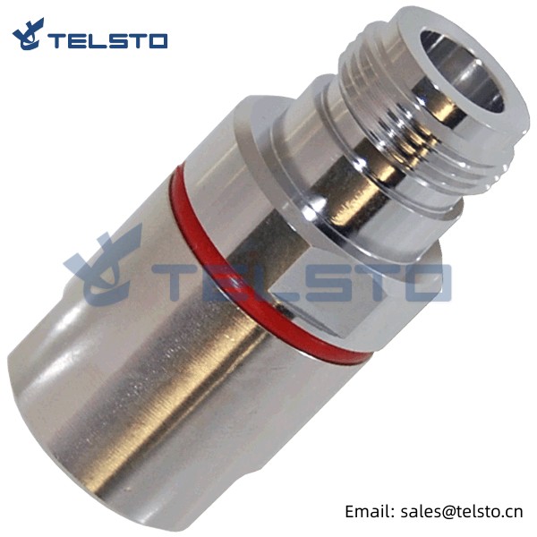
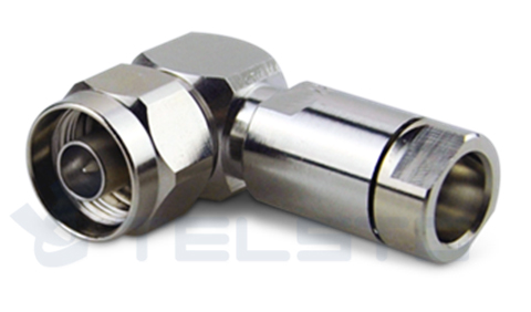
Rf coaxial N type right angle coaxial cable connector N male to 1/2’’superflex cable
Application
Antennas/ Base station /Broad cast /Cable assembly /Cellular /Components /Instrumentation/Microwave Radio/Mil-Aero
PCS/Radar /Radios/Satcom /Surge protection WLAN
Our Service
1. We also customize special products to meet our clients' requirements. Just show us your drawing, sample or indicated details, we will produce it or please kindly send us your specific engineering parameters such as IMD, VSWR, plating etc.
2. Sample is OK to provide.
3. We will reply you for your inquiry in 24 hours.
Related
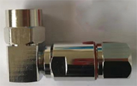
Model: TEL-NMA.12S-RFC
Description
N Male Angle connector for 1/2″ Superflexible cable
| Material and Plating | |
| Center contact | Brass / Silver Plating |
| Insulator | PTFE |
| Body & Outer Conductor | Brass / alloy plated with tri-alloy |
| Gasket | Silicon Rubber |
| Electrical Characteristics | |
| Characteristics Impedance | 50 Ohm |
| Frequency Range | DC~3 GHz |
| Insulation Resistance | ≥5000MΩ |
| Dielectric Strength | ≥2500 V rms |
| Center contact resistance | ≤1.0 mΩ |
| Outer contact resistance | ≤0.2 mΩ |
| Insertion Loss | ≤0.12dB@3GHz |
| VSWR | ≤1.1@-3.0GHz |
| Temperature range | -40~85℃ |
| PIM dBc(2×20W) | ≤-160 dBc(2×20W) |
| Waterproof | IP67 |
Installation Instructions of N or 7 / 16 or 4310 1 / 2″ super flexible cable
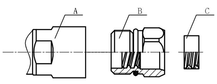
Structure of connector: ( Fig1 )
A. front nut
B. back nut
C. gasket
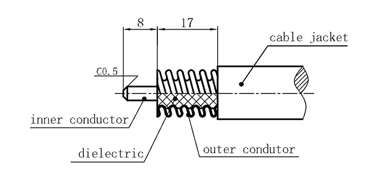
Stripping dimensions is as shown by diagram ( Fig2 ), attention should be paid while stripping:
1. The end surface of inner conductor should be chamfered.
2. Remove impurities such as copper scale and burr on the end surface of the cable.
Assembling the sealing part: Screw the sealing part in along the outer conductor of the cable as shown by the diagram ( Fig3).
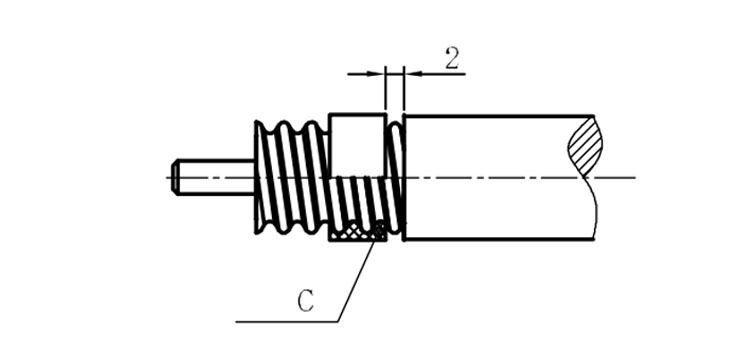
Assembling the back nut (Fig3).
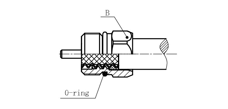
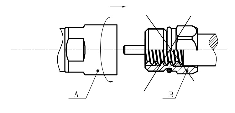
Combine the front and back nut by screwing as shown by diagram ( Figs( 5)
1. Before screwing, smear a layer of lubricating grease on the o-ring.
2. Keep the back nut and the cable motionless, Screw on main shell body on back shell body. Screw down main shell body of back shell body using monkey wrench. Assembling is finished.
