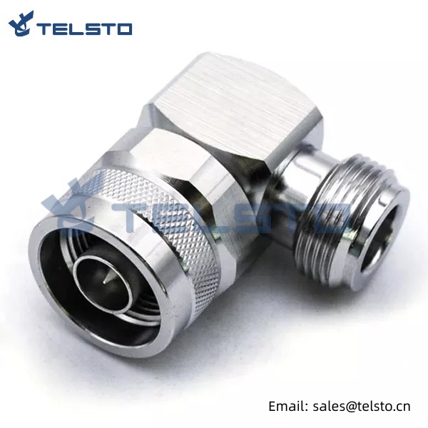
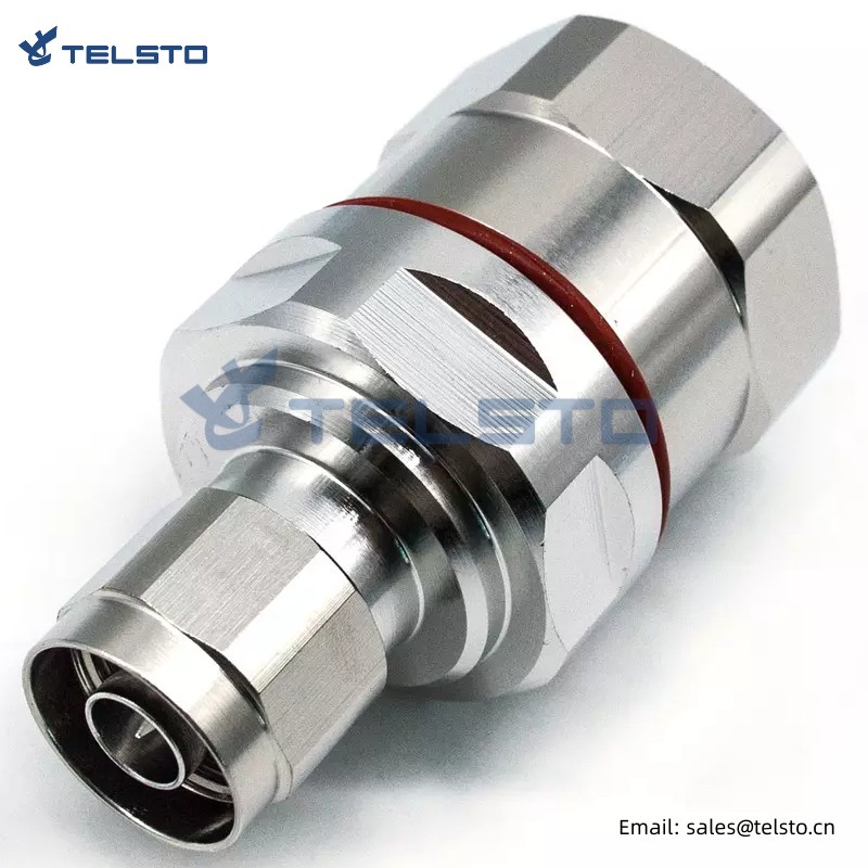
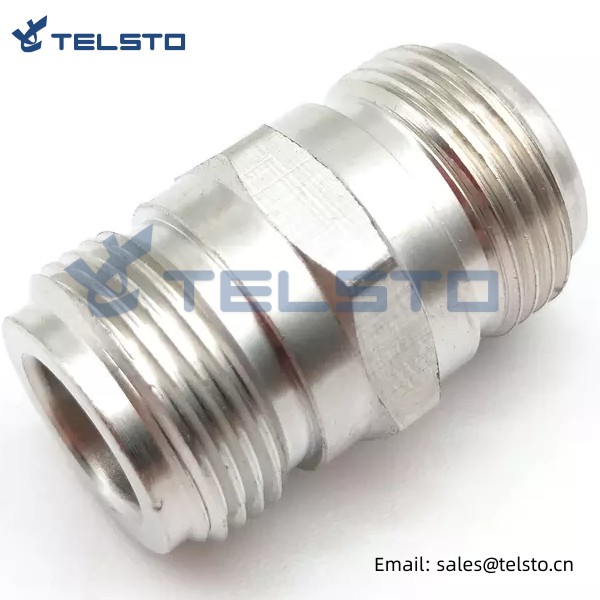
RF Coaxial N male to N female right angle adaptor connector
Telsto RF connector is a high-performance radio connector with a working frequency range of DC-3 GHz, excellent VSWR performance and low passive intermodulation. This kind of connector is very suitable for cellular base stations, distributed antenna systems (DAS) and cell applications, because these applications require high-frequency and high-performance connectors to ensure the quality and stability of signal transmission.
At the same time, the coaxial adapter is also a very practical radio tool. It can quickly change the gender or connector type of the terminated cable, so that users can flexibly adjust the configuration and connection mode of the radio equipment to adapt to different application requirements. No matter in the laboratory, production line or practical application, coaxial adapter is a very important tool. It can greatly simplify the connection process, improve work efficiency, and reduce the possibility of misoperation and connection errors, so as to ensure the safety and reliability of radio equipment.
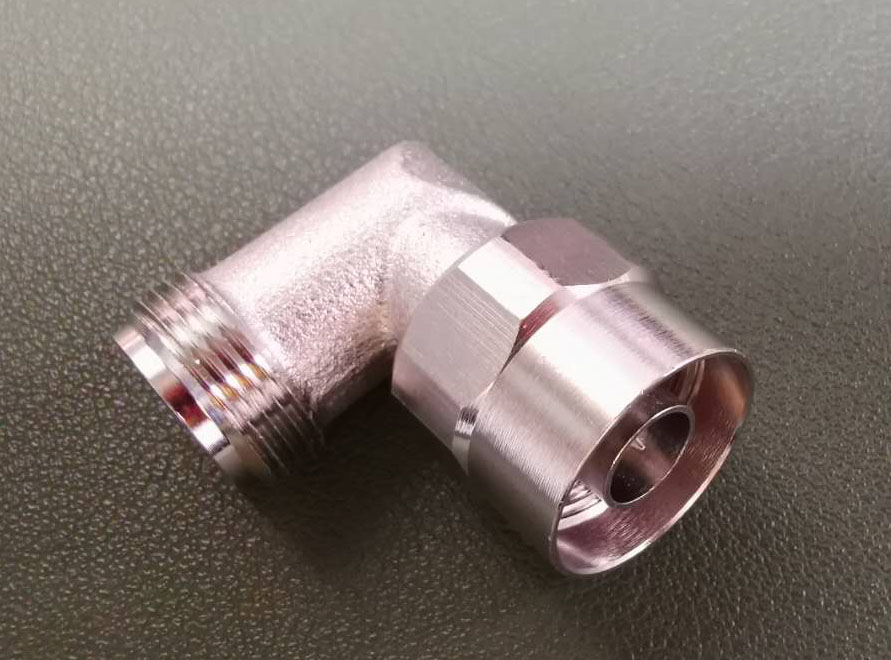
Telsto RF Coaxial N male to N female right angle adaptor connector design with a 50 Ohm impedance. It is manufactured to precise RF adapter specifications and has a maximum VSWR of 1.15:1.
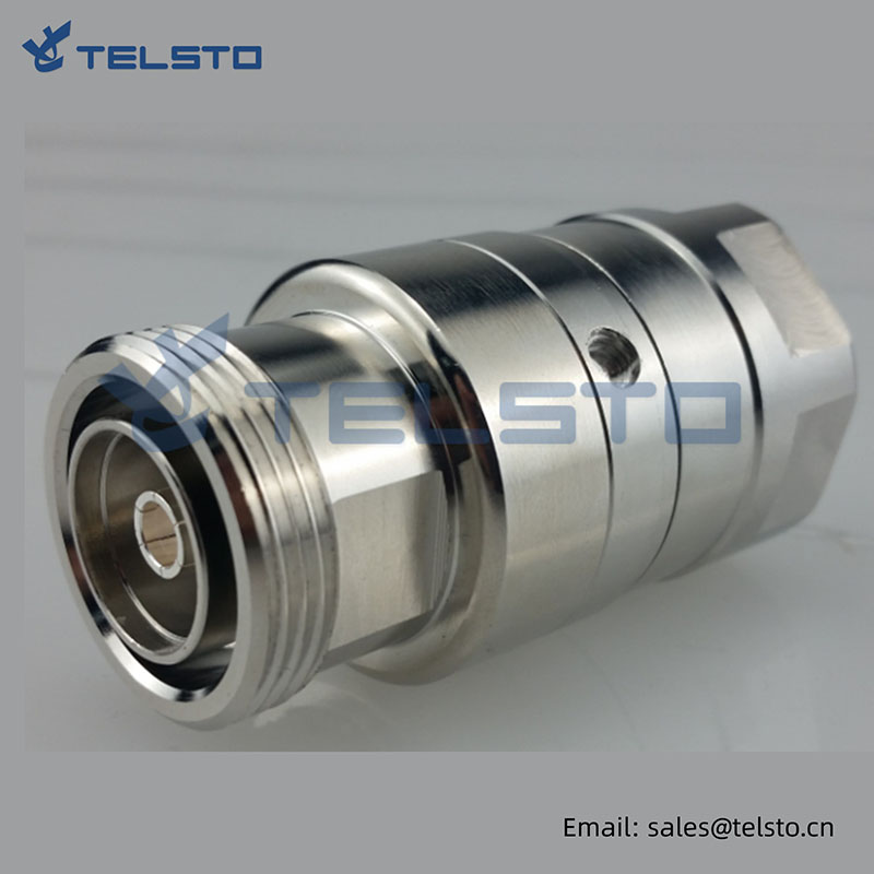
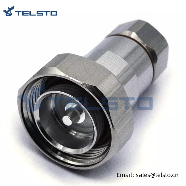
4.3-10 types for your choices
| Product | Description | Part No. |
| RF Adapter | 4.3-10 Female to Din Female Adapter | TEL-4310F.DINF-AT |
| 4.3-10 Female to Din Male Adapter | TEL-4310F.DINM-AT | |
| 4.3-10 Male to Din Female Adapter | TEL-4310M.DINF-AT | |
| 4.3-10 Male to Din Male Adapter | TEL-4310M.DINM-AT |
Related
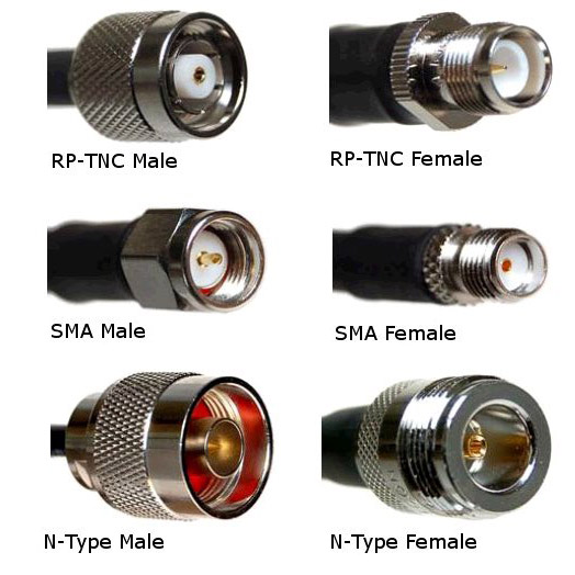
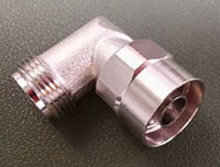
Model: TEL-NM.NFA-AT
Description
N Male to N Female Right Angle Adapter
| Material and Plating | |
| Center contact | Brass / Silver Plating |
| Insulator | PTFE |
| Body & Outer Conductor | Brass / alloy plated with tri-alloy |
| Gasket | Silicon Rubber |
| Electrical Characteristics | |
| Characteristics Impedance | 50 Ohm |
| Frequency Range | DC~3 GHz |
| Insulation Resistance | ≥5000MΩ |
| Dielectric Strength | ≥2500 V rms |
| Center contact resistance | ≤1.0 mΩ |
| Outer contact resistance | ≤0.25 mΩ |
| Insertion Loss | ≤0.1dB@3GHz |
| VSWR | ≤1.1@-3.0GHz |
| Temperature range | -40~85℃ |
| PIM dBc(2×20W) | ≤-160 dBc(2×20W) |
| Waterproof | IP67 |
Installation Instructions of N or 7 / 16 or 4310 1 / 2″ super flexible cable
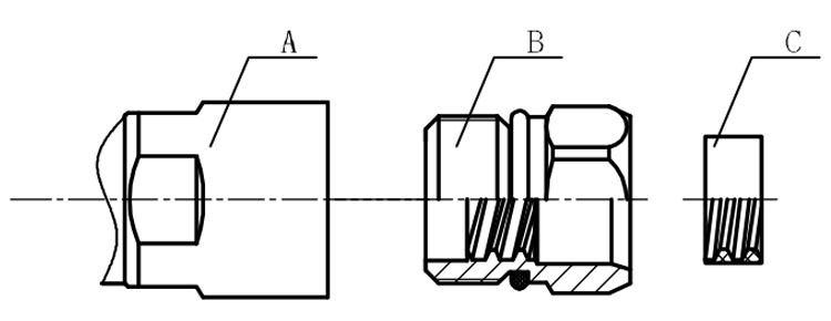
Structure of connector: ( Fig1 )
A. front nut
B. back nut
C. gasket
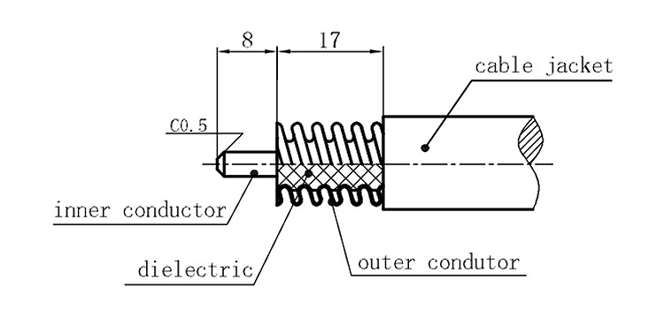
Stripping dimensions is as shown by diagram ( Fig2 ), attention should be paid while stripping:
1. The end surface of inner conductor should be chamfered.
2. Remove impurities such as copper scale and burr on the end surface of the cable.
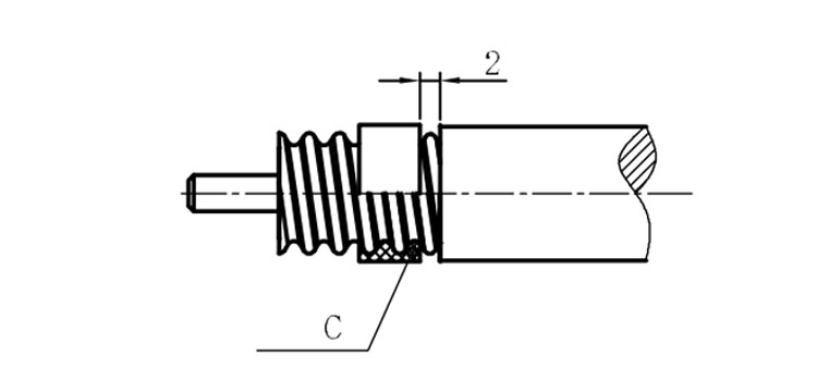
Assembling the sealing part: Screw the sealing part in along the outer conductor of the cable as shown by the diagram ( Fig3).
Assembling the back nut (Fig3).
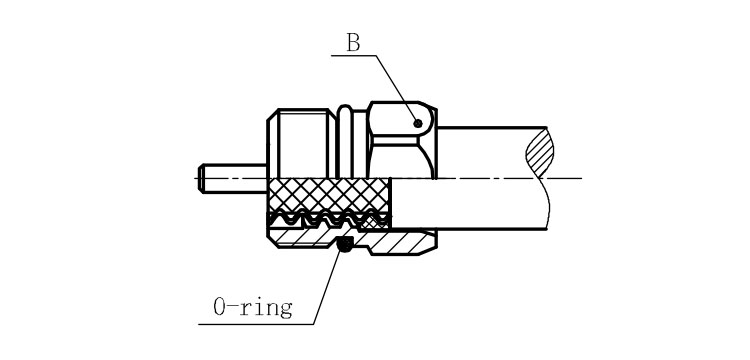
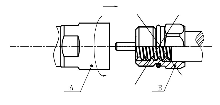
Combine the front and back nut by screwing as shown by diagram ( Figs( 5)
1. Before screwing, smear a layer of lubricating grease on the o-ring.
2. Keep the back nut and the cable motionless, Screw on main shell body on back shell body. Screw down main shell body of back shell body using monkey wrench. Assembling is finished.
Our company has multiple advantages
1. Our high standard quality makes us stand out in the market. We not only provide customers with high-quality products and services, but also have been committed to improving quality standards through continuous optimization and innovation to ensure that we always provide the best quality products and services.
2. Our price is the most competitive. We realize that in a highly competitive market, price is a very important consideration. Therefore, we strive to maintain our price advantage, provide customers with affordable solutions, and help customers achieve higher cost performance.
3. We provide the best customized telecommunications solutions. We deeply understand customers’ needs and requirements, and provide them with the best solutions according to their specific needs and budgets. Our goal is to ensure that customers get the best solution for them and make their business more efficient and successful.

