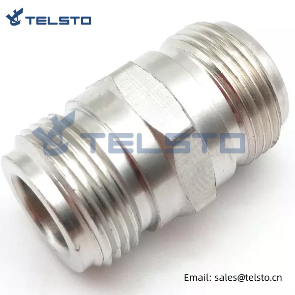
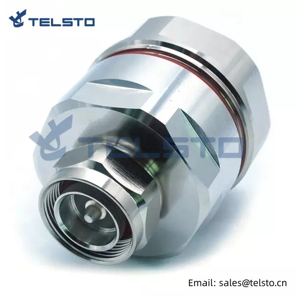
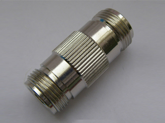
RF Coaxial N Female to N Female Adapter Connector
Telsto RF Adapter has an operational frequency range of DC-6 GHz, offers excellent VSWR performance and Low Passive Inter modulation. This makes it ideally suited for use in cellular base stations, distributed antenna systems (DAS) and small cell applications.
Our N to N female adapter is a coaxial adapter design with a 50 Ohm impedance. This 50 Ohm N adapter is manufactured to precise RF adapter specifications and has a maximum VSWR of 1.5:1.
This type of coaxial adapter is a straight body style and is constructed with female gender on both side. This straight N female connector adapter is an in-line RF adapter design.
|
Product |
Description | Part No. |
|
RF Adapter |
4.3-10 Female to Din Female Adapter | TEL-4310F.DINF-AT |
| 4.3-10 Female to Din Male Adapter | TEL-4310F.DINM-AT | |
| 4.3-10 Female to N Male Adapter | TEL-4310F.NM-AT | |
| 4.3-10 Male to Din Female Adapter | TEL-4310M.DINF-AT | |
| 4.3-10 Male to Din Male Adapter | TEL-4310M.DINM-AT | |
| 4.3-10 Male to N Female Adapter | TEL-4310M.NF-AT | |
| Din Female to Din Male Right Angle Adapter | TEL-DINF.DINMA-AT | |
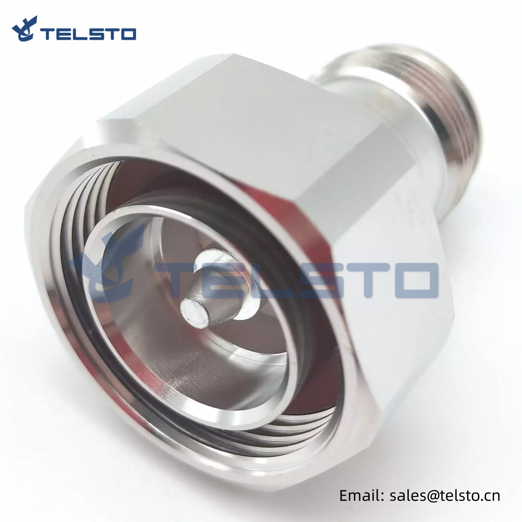
| N Female to Din Male Adapter | TEL-NF.DINM-AT | |
| N Female to N Female Adapter | TEL-NF.NF-AT | |
| N Male to Din Female Adapter | TEL-NM.DINF-AT | |
| N Male to Din Male Adapter | TEL-NM.DINM-AT | |
| N Male to N Female Adapter | TEL-NM.NF-AT | |
| N Male to N Male Right Angle Adapter | TEL-NM.NMA.AT | |
| N Male to N Male Adapter | TEL-NM.NM-AT | |
| 4.3-10 Female to 4.3-10 Male Right Angle Adapter | TEL-4310F.4310MA-AT | |
| DIN Female to Din Male Right Angle RF Adapter | TEL-DINF.DINMA-AT | |
| N Female Right Angle to N Female RF Adapter | TEL-NFA.NF-AT | |
| N Male to 4.3-10 Female Adapter | TEL-NM.4310F-AT | |
| N Male to N Female Right Angle Adapter | TEL-NM.NFA-AT |
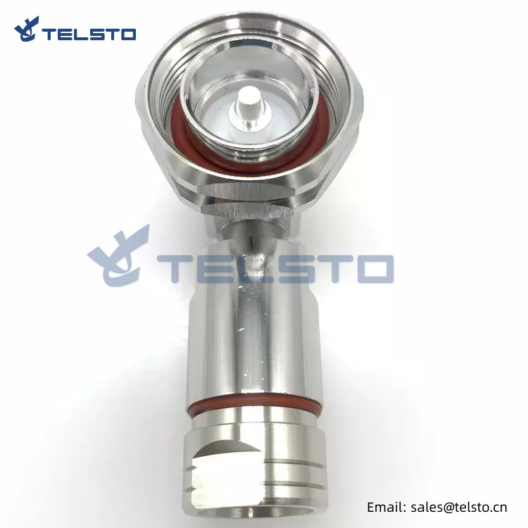
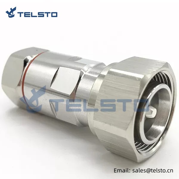
N Female to N Female Coax Adapter Double Female Jack Connector
● Allows interconnection of devices with N female interfaces.
● Use for Coaxial extension, coaxial interface conversion, coax retrofit applications.
● RoHS compliant.
FAQ
What about your quality?
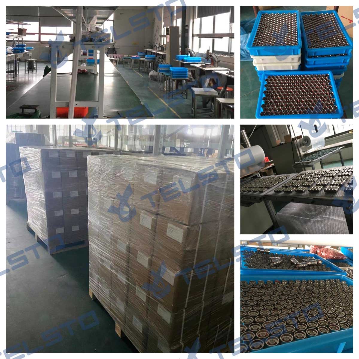
All products we supply are strictly tested by our QC department or third party inspection standard or better before shipment. Most of goods such as coaxial jumper cables, passive devices, etc. are 100% tested.
Can you offer samples to test before placing formal order?
Sure, free samples can be provided. We are also glad to support our clients to develop new products together to help them to develop the local market.
Do you accept customization?
Yes, we are customizing products according to the customer's requirements.
How long is the delivery time?
Usually we keep stocks, so delivery is fast. For bulk orders, it will be up to the demand.
What is the shipping methods?
Flexible shipping methods per customer's urgency, such as DHL, UPS, Fedex, TNT, by air, by sea are all acceptable.
Can our logo or company name can be printed on your products or the packages?
Yes, OEM service is available.
Is the MOQ fixed?
MOQ is flexible and we accept small order as trial order or sample testing.
Related
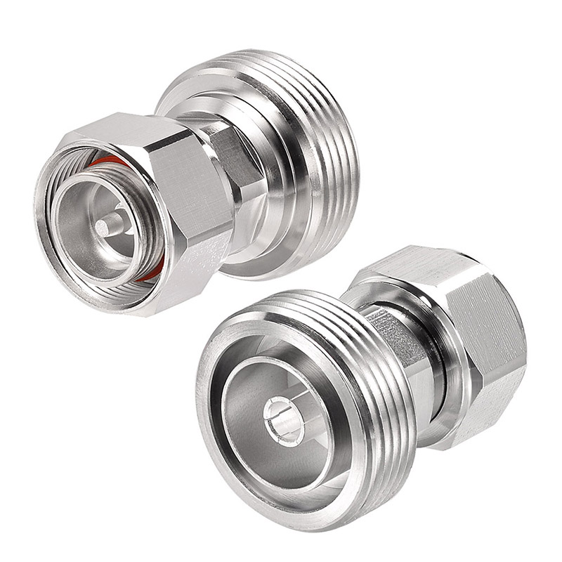
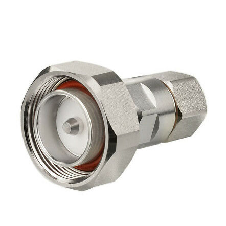
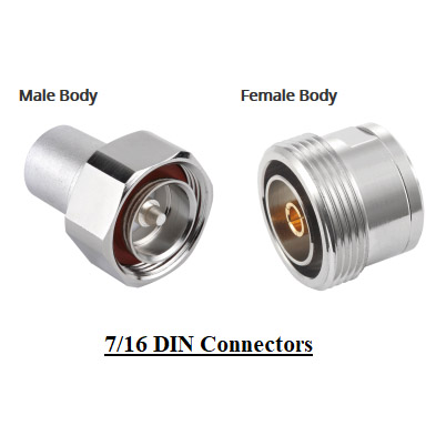
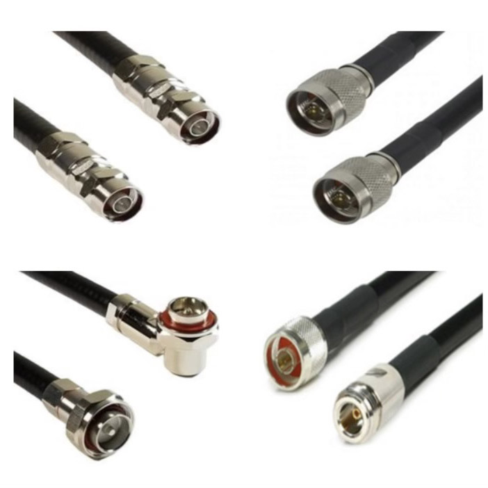
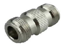
Model: TEL-NF.NF-AT
Description
N Female to N Female Adapter
| Material and Plating | ||
| Material | plating | |
| Body | Brass | Trimetal Plating |
| Insulator | PTFE | TPX |
| Inner conductor Pin | Brass | Silver Plating |
| Inner conductor Socket | Tin Bronze | Silver Plating |
| Electrical Characteristics | ||
| Characteristics Impedance | 50 Ohm | |
| Frequency Range | 0~11 GHz | |
| VSWR | ≤1.08@0.8~1.0GHz,≤1.10@1.7~2.7GH | |
| Insertion loss | ≤ 0.17dB@3GHz | |
| Inner Conductor Contact Resistance | ≤ 1.00mΩ | |
| Outer Conductor Contact Resistance | ≤ 0.40mΩ | |
| Dielectric Strength | 2500V | |
| Insulation Resistance | ≥5000MΩ | |
| Shielding Efficiency | ≥120dB | |
| Gasket | Silicon Rubber | |
| Environmental | ||
| Temperature range | -45~+85℃ | |
Installation Instructions of N or 7 / 16 or 4310 1 / 2″ super flexible cable
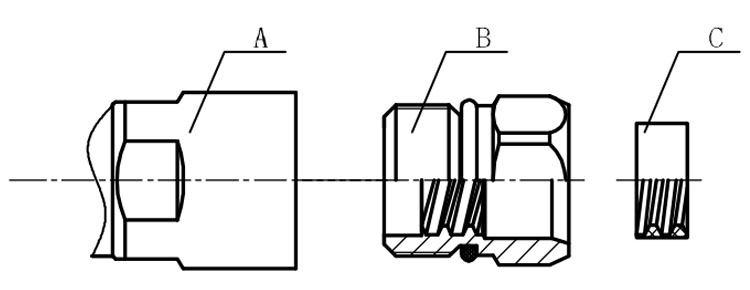
Structure of connector: ( Fig1 )
A. front nut
B. back nut
C. gasket
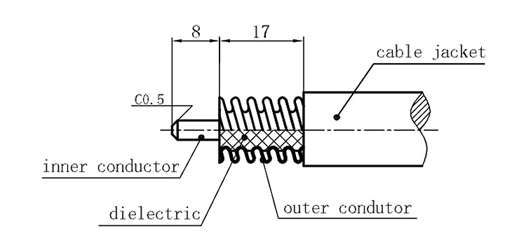
Stripping dimensions is as shown by diagram ( Fig2 ), attention should be paid while stripping:
1. The end surface of inner conductor should be chamfered.
2. Remove impurities such as copper scale and burr on the end surface of the cable.
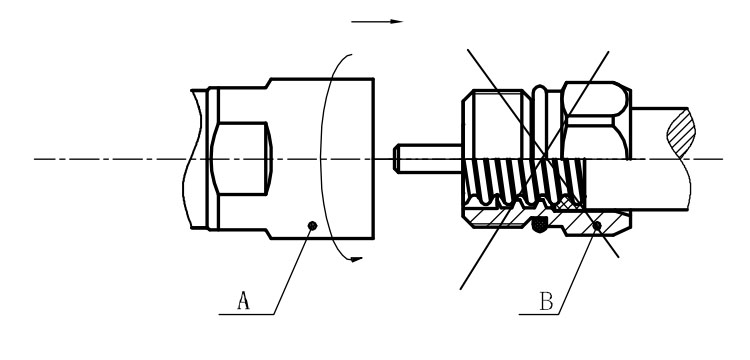
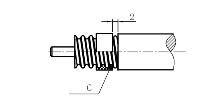
Assembling the sealing part: Screw the sealing part in along the outer conductor of the cable as shown by the diagram ( Fig3).
Assembling the back nut (Fig3).
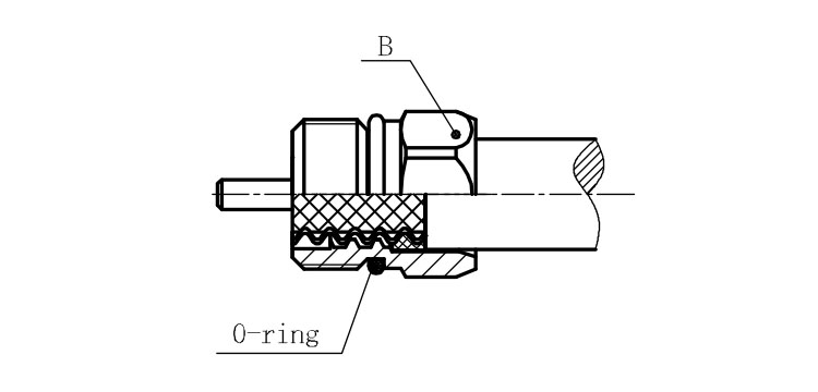
Combine the front and back nut by screwing as shown by diagram ( Figs( 5)
1. Before screwing, smear a layer of lubricating grease on the o-ring.
2. Keep the back nut and the cable motionless, Screw on main shell body on back shell body. Screw down main shell body of back shell body using monkey wrench. Assembling is finished.
