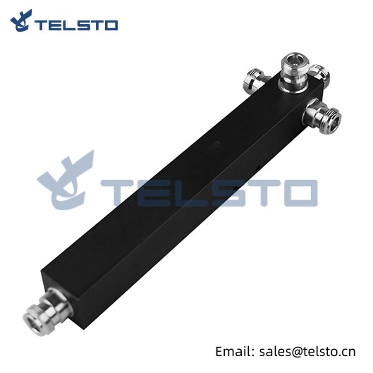
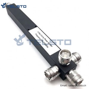
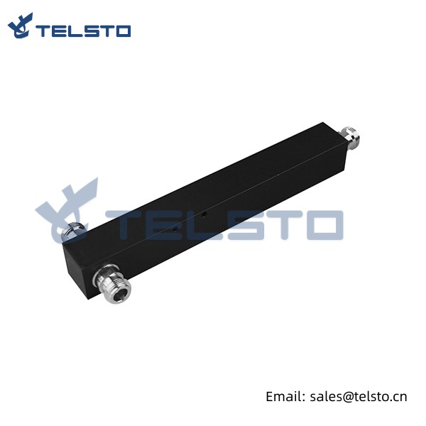
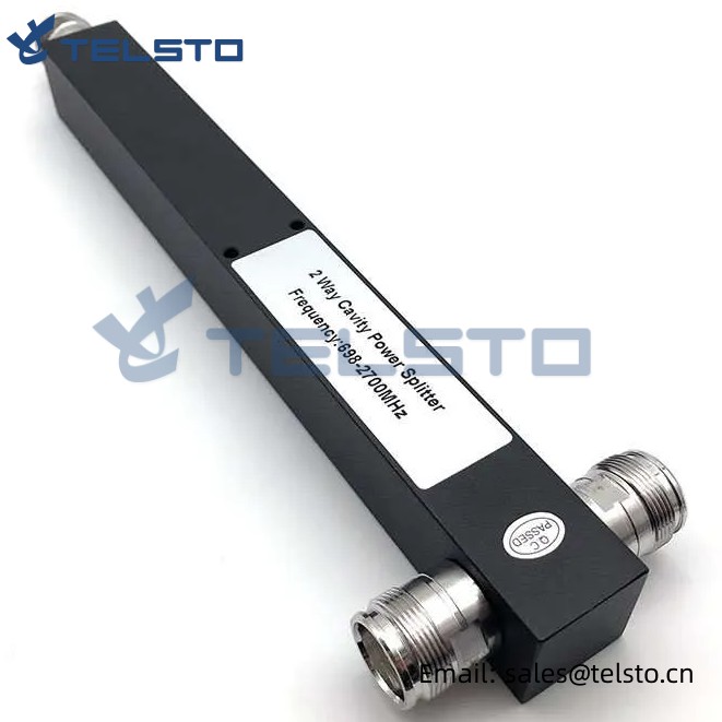
RF 698-2700MHz N Female connector 4 way Power Splitter
Multiple-Band Frequency Ranges
300 Watt Power Rating
High Reliability
Low Cost Design for ease of mounting
N-Female Connector
| General Specification | TEL-PS-2 | TEL-PS-3 | TEL-PS-4 |
| Frequency Range (MHz) | 698-2700 | ||
| Way No(dB)* | 2 | 3 | 4 |
| Divided Loss(dB) | 3 | 4.8 | 6 |
| VSWR | ≤1.20 | ≤1.25 | ≤1.30 |
| Insertion Loss(dB) | ≤0.20 | ≤0.30 | ≤0.40 |
| PIM3(dBc) | ≤-150(@+43dBm×2) | ||
| Impedance (Ω) | 50 | ||
| Power Rating(W) | 300 | ||
| Power peak (W) | 1000 | ||
| Connector | N-F | ||
| Temperature Range(℃) | -20~+70 | ||
Installation Instructions of N or 7 / 16 or 4310 1 / 2″ super flexible cable
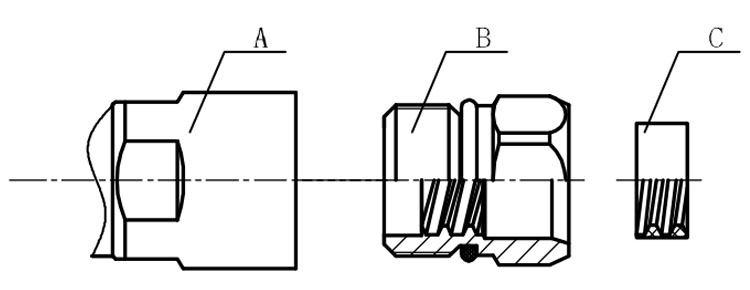
Structure of connector: ( Fig1 )
A. front nut
B. back nut
C. gasket
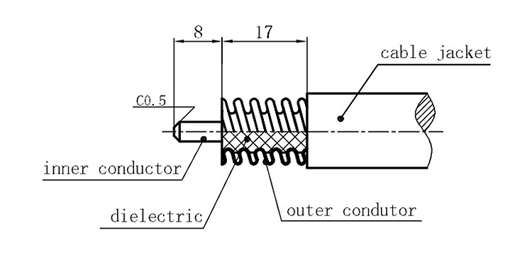
Stripping dimensions is as shown by diagram ( Fig2 ), attention should be paid while stripping:
1. The end surface of inner conductor should be chamfered.
2. Remove impurities such as copper scale and burr on the end surface of the cable.
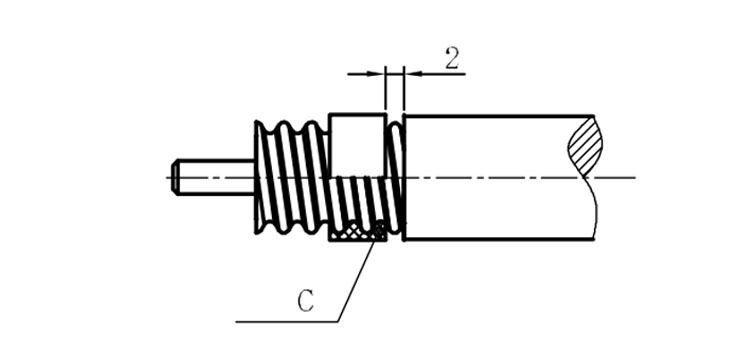
Assembling the sealing part: Screw the sealing part in along the outer conductor of the cable as shown by the diagram ( Fig3).
Assembling the back nut (Fig3).
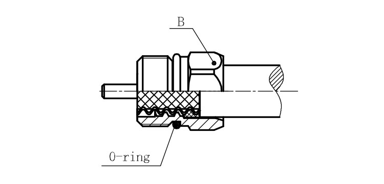
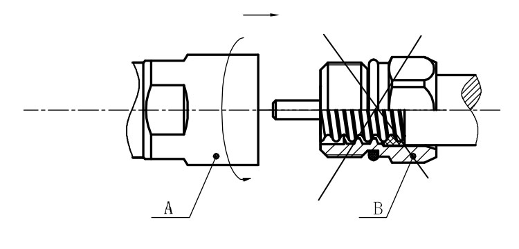
Combine the front and back nut by screwing as shown by diagram ( Figs( 5)
1. Before screwing, smear a layer of lubricating grease on the o-ring.
2. Keep the back nut and the cable motionless, Screw on main shell body on back shell body. Screw down main shell body of back shell body using monkey wrench. Assembling is finished.
