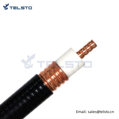
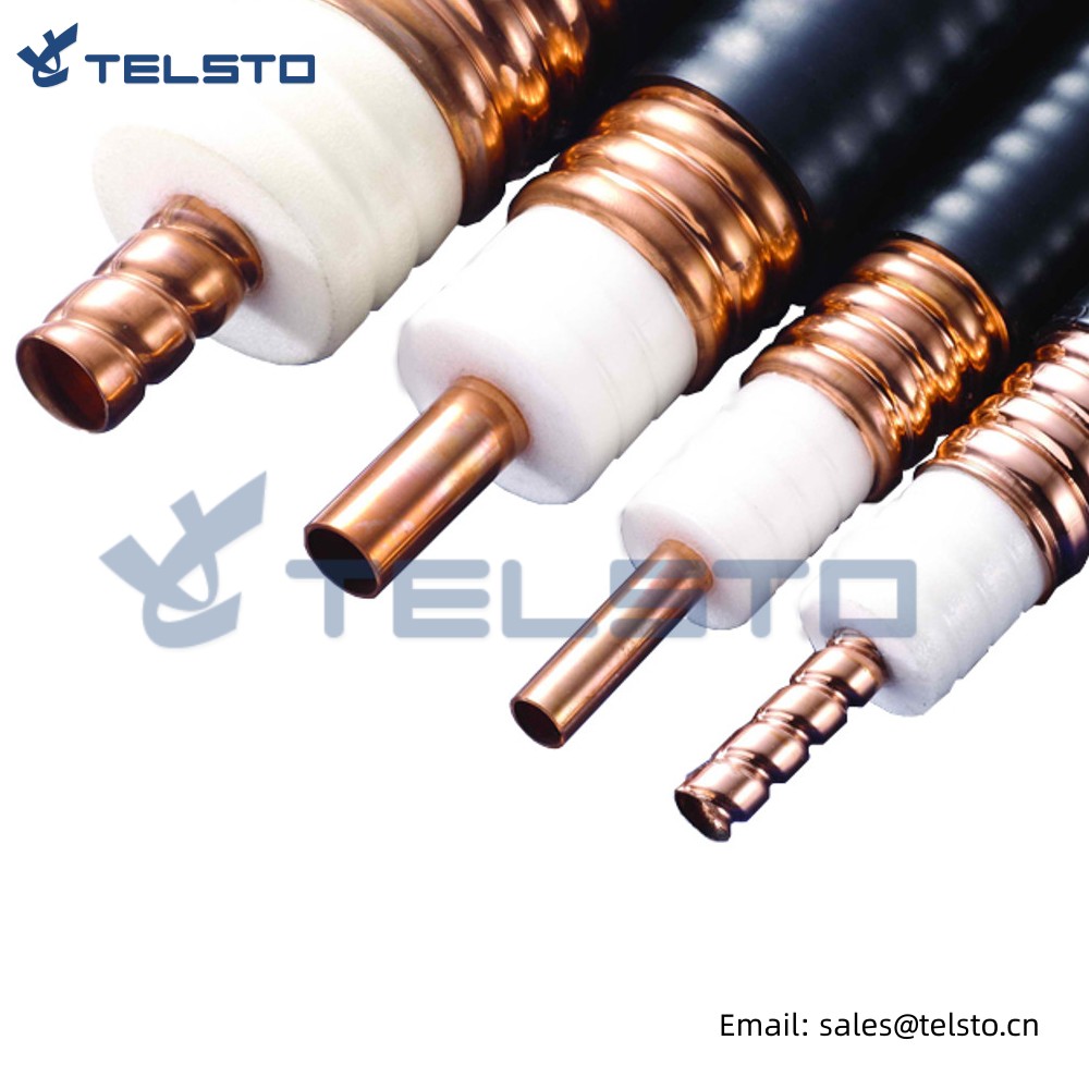
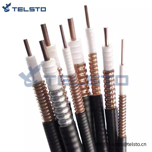
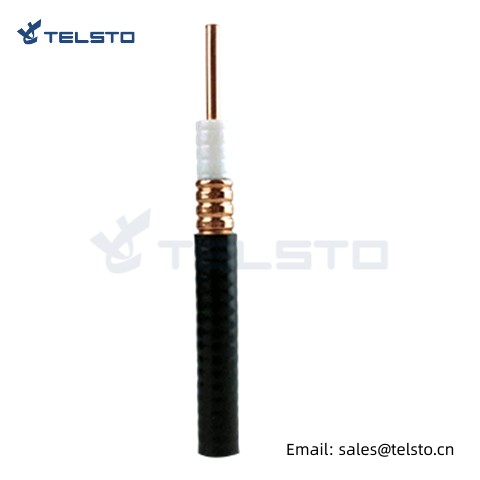
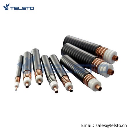
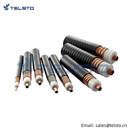
High Quality Coaxial Feeder Cable 7/8″ Fire Retardant
| Construction | |||
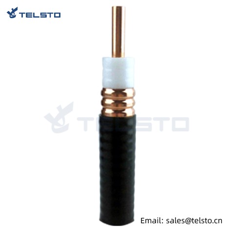
| inner conductor | material | smooth copper tube | |
| dia. | 8.80±0.10 mm | ||
| insulation | material | physically foamed PE | |
| dia. | 22.20±0.40 mm | ||
| outer conductor | material | ring corrugated copper | |
| diameter | 24.90±0.30 mm | ||
| jacket | material | Fire retardant PE | |
| diameter | 27.30±0.20 mm | ||
| mechanical properties | |||
| bending radius | singlerepeatedmoving | 120 mm250 mm500 mm | |
| pulling strength | 1470 N | ||
| crush resistance | 1.4 kg/mm | ||
| recommended temperature | PE jacket | store | -70±85°C |
| installation | -40±60°C | ||
| operation | -55±85°C | ||
| fire retardant PE jacket | store | -30±80°C | |
| installation | -25±60°C | ||
| operation | -30±80°C | ||
| electrical properties | |||
| impedance | 50±2 Ω | ||
| capacitance | 75 pF/m | ||
| inductance | 0.187 uH/m | ||
| propagation velocity | 88 % | ||
| DC breakdown voltage | 6.0 kV | ||
| insulation resistance | >5000 MQ.km | ||
| peak power | 91 kW | ||
| screening attenuation | >120 dB | ||
| cut-off frequency | 5.5 GHz | ||
| attenuation and average power | |||
| frequency, MHz | power rate@20°C,kW | nom.attenuation@20°C,dB/100m | |
| 10 | 24.6 | 0.366 | |
| 100 | 7.56 | 1.19 | |
| 450 | 3.41 | 2.65 | |
| 690 | 2.85 | 3.35 | |
| 800 | 2.48 | 3.63 | |
| 900 | 2.33 | 3.88 | |
| 1000 | 2.19 | 4.12 | |
| 1800 | 1.57 | 5.75 | |
| 2000 | 1.48 | 6.11 | |
| 2200 | 1.41 | 6.45 | |
| 2400 | 1.34 | 6.79 | |
| 2500 | 1.30 | 6.95 | |
| 2600 | 1.27 | 7.12 | |
| 2700 | 1.25 | 7.28 | |
| 3000 | 1.16 | 7.76 | |
| maximum attenuation value may be 105% of the nominal attenuaiton value. | |||
| vswr | |||
| 820-960MHz | ≤1.15 | ||
| 1700-2200MHz | ≤1.15 | ||
| 2300-2400MHz | ≤1.15 | ||
| standards | |||
| 2011/65/EU | compliant | ||
| IEC61196.1-2005 | compliant | ||
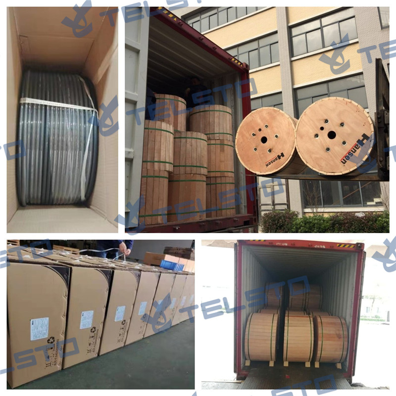
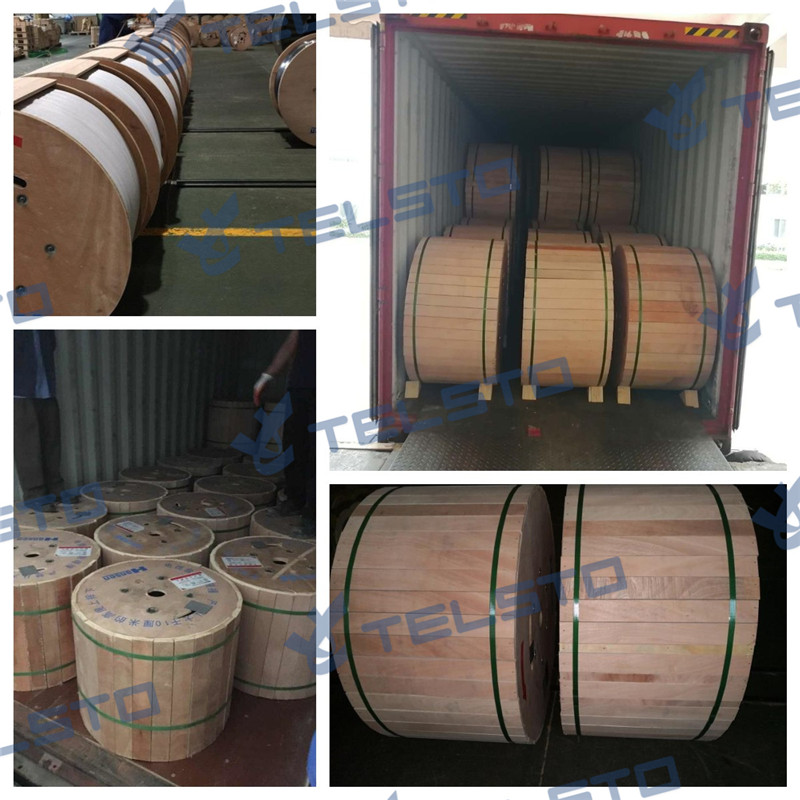
Packing Reference
Installation Instructions of N or 7 / 16 or 4310 1 / 2″ super flexible cable
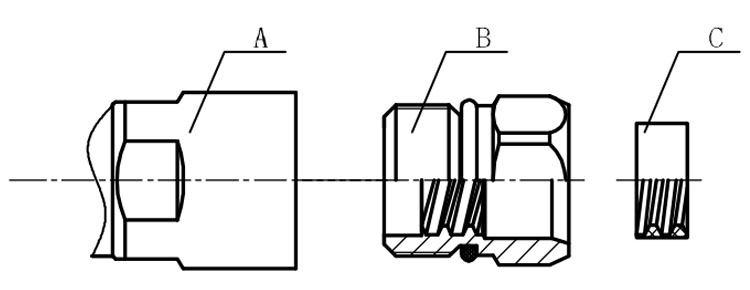
Structure of connector: ( Fig1 )
A. front nut
B. back nut
C. gasket
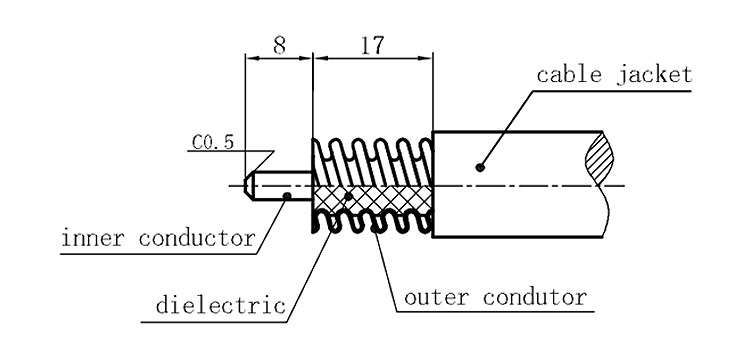
Stripping dimensions is as shown by diagram ( Fig2 ), attention should be paid while stripping:
1. The end surface of inner conductor should be chamfered.
2. Remove impurities such as copper scale and burr on the end surface of the cable.
Assembling the sealing part: Screw the sealing part in along the outer conductor of the cable as shown by the diagram ( Fig3).
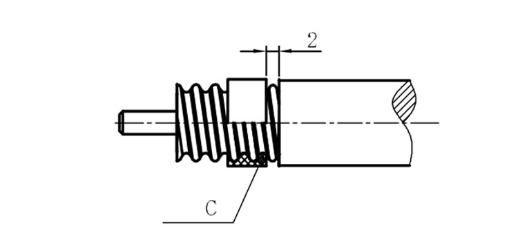
Assembling the back nut (Fig3).
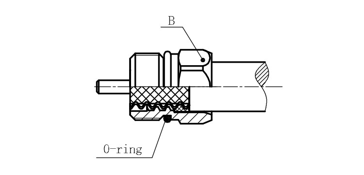
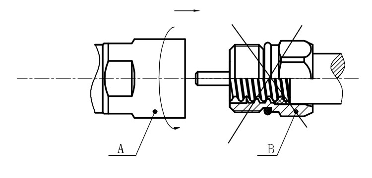
Combine the front and back nut by screwing as shown by diagram ( Figs( 5)
1. Before screwing, smear a layer of lubricating grease on the o-ring.
2. Keep the back nut and the cable motionless, Screw on main shell body on back shell body. Screw down main shell body of back shell body using monkey wrench. Assembling is finished.
