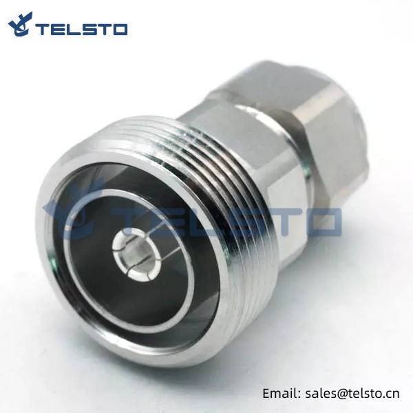
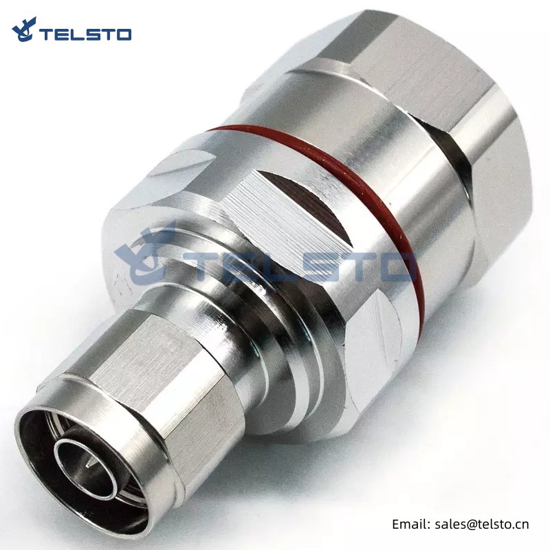
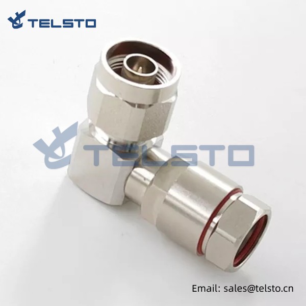
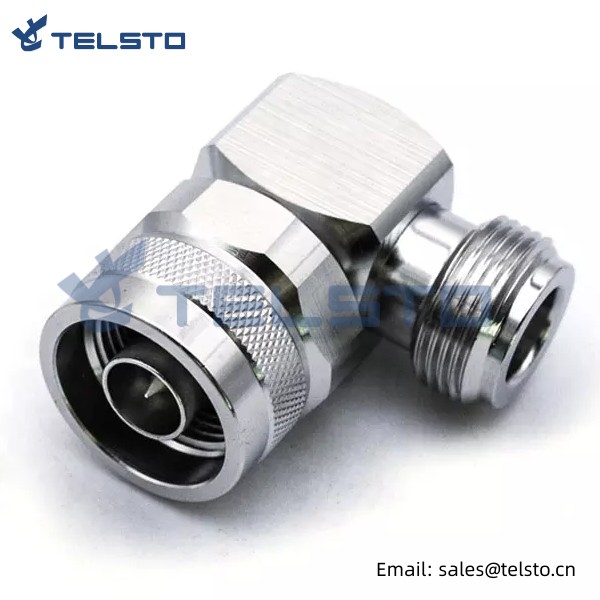
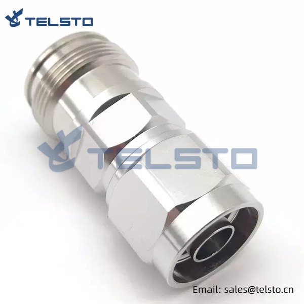
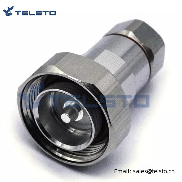
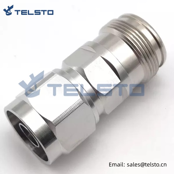
7/16 DIN Female to N Male RF Coaxial Adapter Connector
Telsto RF Connector has an operational frequency range of DC-3 GHz, offers excellent VSWR performance and Low Passive Inter modulation. This makes it ideally suited for use in cellular base stations, distributed antenna systems (DAS) and small cell applications.
Coax adapters are the perfect way to quickly change the gender or connector type on an already terminated cable.
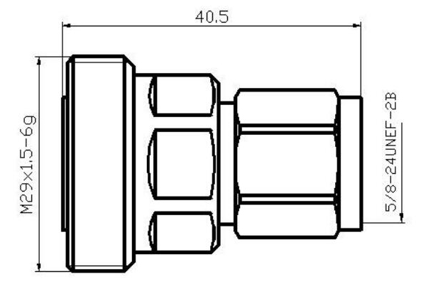
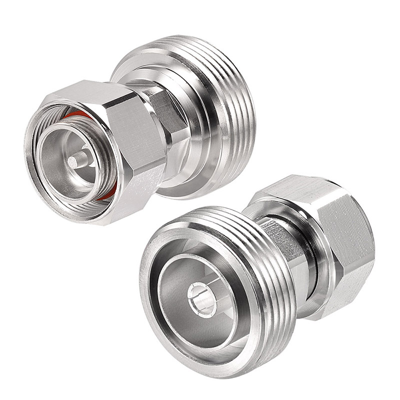
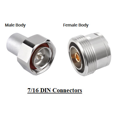
This nickel-plated coaxial adapter has an N male connector opposite an 7/16 DIN female connector.7/16 DIN female to N male coaxial adapter is a straight body style. This straight 7/16 DIN connector adapter is an in-line RF adapter design.
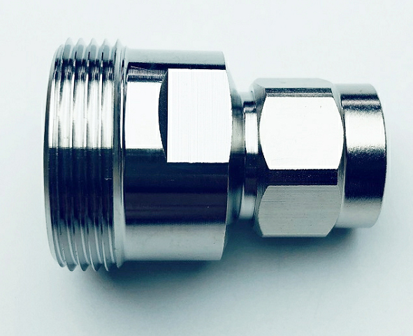
Our 7/16 DIN to N adapter is a coaxial adapter design with a 50 Ohm impedance. This 50 Ohm 7/16 DIN adapter is manufactured to precise RF adapter specifications and has a maximum VSWR of 1.15:1.
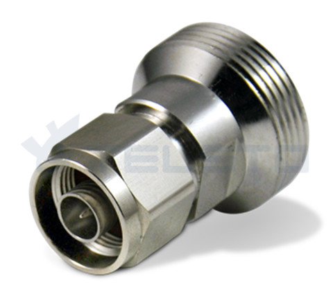
● All materials are RoHS compliant.
● Competitive price.
● OEM service offered.
● We are able to supply various types of connectors according to clients' requirement.
4.3-10 types for your choices
| Product | Description | Part No. |
| RF Adapter | 4.3-10 Female to Din Female Adapter | TEL-4310F.DINF-AT |
| 4.3-10 Female to Din Male Adapter | TEL-4310F.DINM-AT | |
| 4.3-10 Male to Din Female Adapter | TEL-4310M.DINF-AT | |
| 4.3-10 Male to Din Male Adapter | TEL-4310M.DINM-AT |
Our Services
1. Reply your enquiry in 24 working hours.
2. Customized design is available. OEM &ODM are welcome.
3. Exclusive and unique solution can be provided to our customer by our well-trained and professional engineers and staffs.
4. Quick delivery time for decent order.
5. Experienced in doing business with large listed companies.
6. Free Samples can be provided.
7. 100% Trade Assurance of payment & quality.
Related
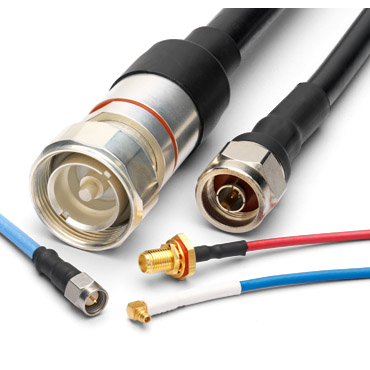
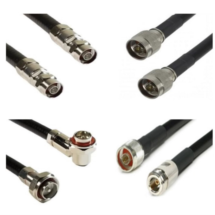
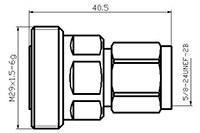
Model: TEL-NM.DINF-AT
Description
N Male to DIN 7/16 Female Adapter
| Material and Plating | |
| Center contact | Brass / Silver Plating |
| Insulator | PTFE |
| Body & Outer Conductor | Brass / alloy plated with tri-alloy |
| Gasket | Silicon Rubber |
| Electrical Characteristics | |
| Characteristics Impedance | 50 Ohm |
| Frequency Range | DC~3 GHz |
| Insulation Resistance | ≥5000MΩ |
| Dielectric Strength | ≥2500 V rms |
| Center contact resistance | ≤1.0 mΩ |
| Outer contact resistance | ≤0.25 mΩ |
| Insertion Loss | ≤0.1dB@3GHz |
| VSWR | ≤1.10@-3.0GHz |
| Temperature range | -40~85℃ |
| PIM dBc(2×20W) | ≤-160 dBc(2×20W) |
| Waterproof | IP67 |
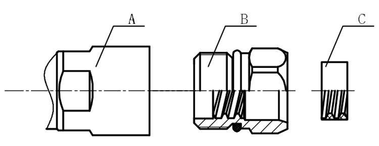
Installation Instructions of N or 7 / 16 or 4310 1 / 2″ super flexible cable
Structure of connector: ( Fig1 )
A. front nut
B. back nut
C. gasket
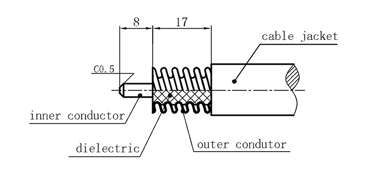
Stripping dimensions is as shown by diagram ( Fig2 ), attention should be paid while stripping:
1. The end surface of inner conductor should be chamfered.
2. Remove impurities such as copper scale and burr on the end surface of the cable.
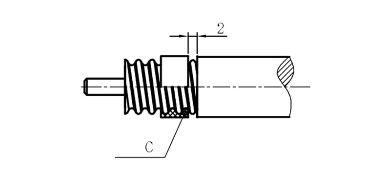
Assembling the sealing part: Screw the sealing part in along the outer conductor of the cable as shown by the diagram ( Fig3).
Assembling the back nut (Fig3).
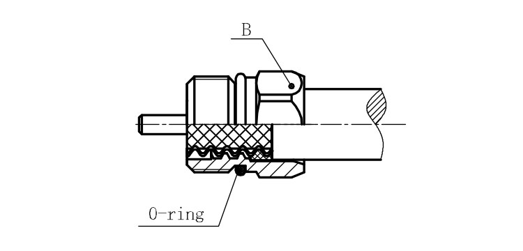
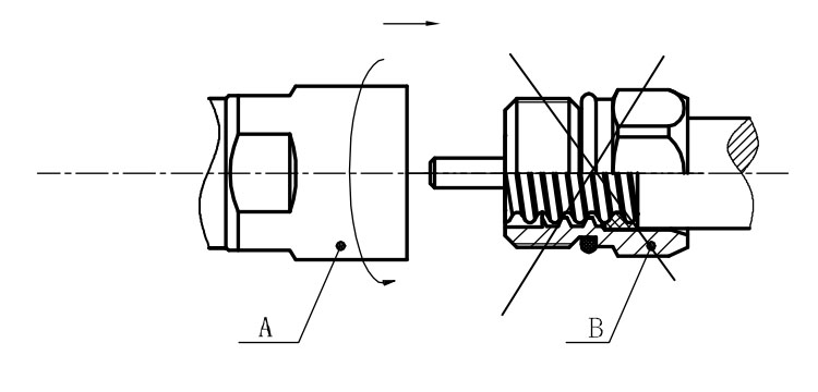
Combine the front and back nut by screwing as shown by diagram ( Figs( 5)
1. Before screwing, smear a layer of lubricating grease on the o-ring.
2. Keep the back nut and the cable motionless, Screw on main shell body on back shell body. Screw down main shell body of back shell body using monkey wrench. Assembling is finished.
