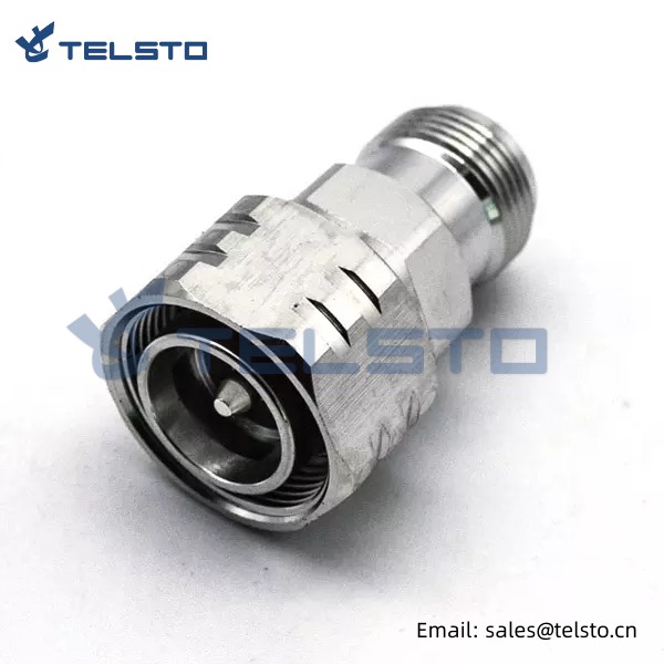
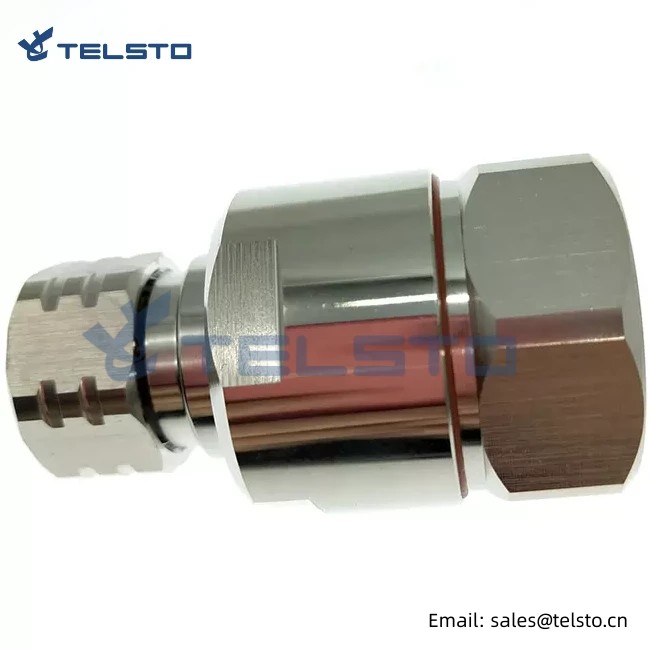
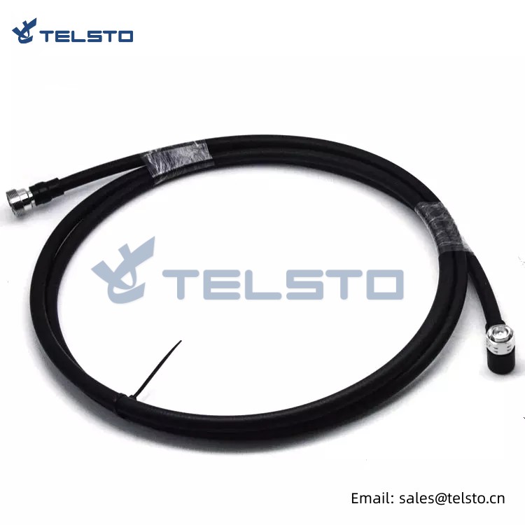
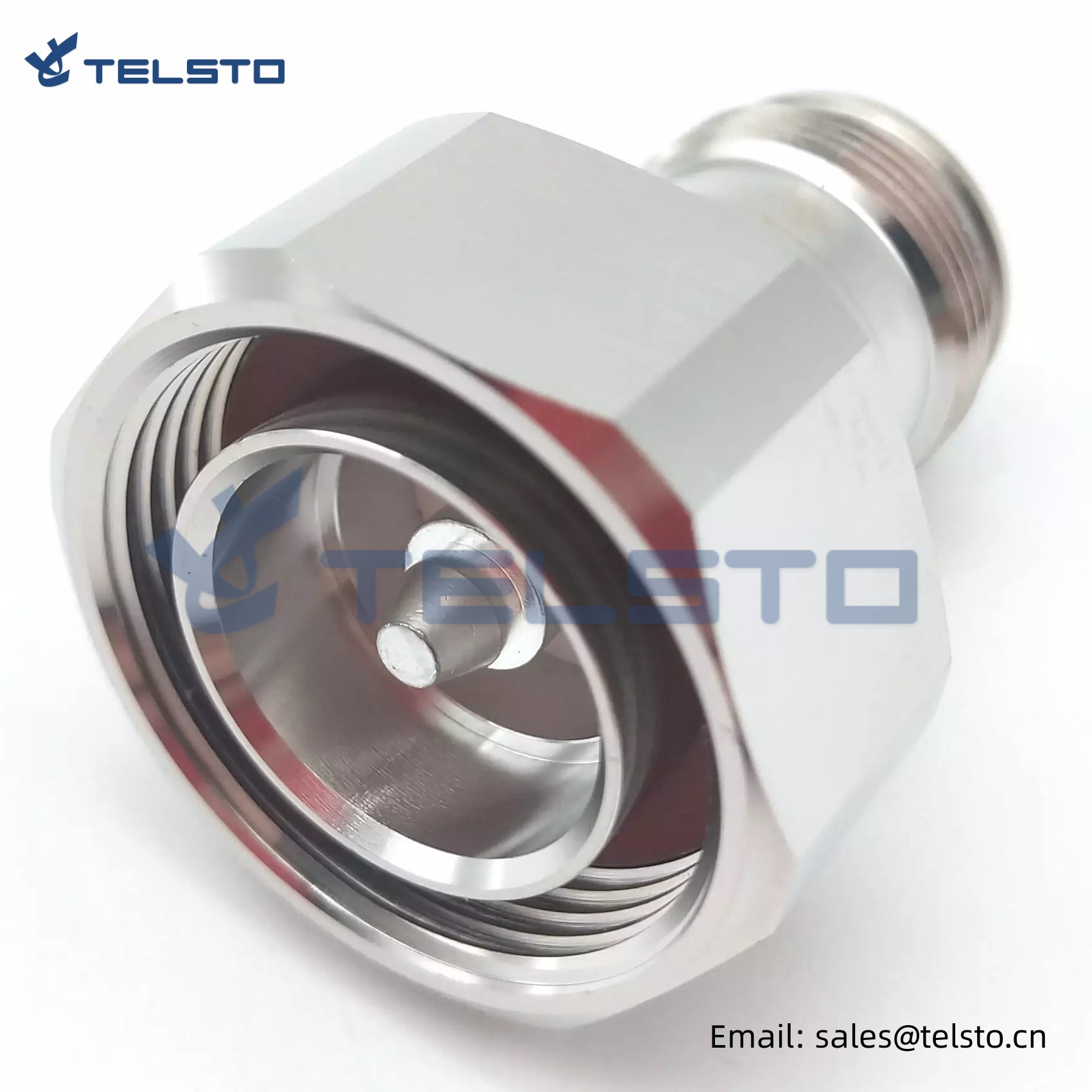
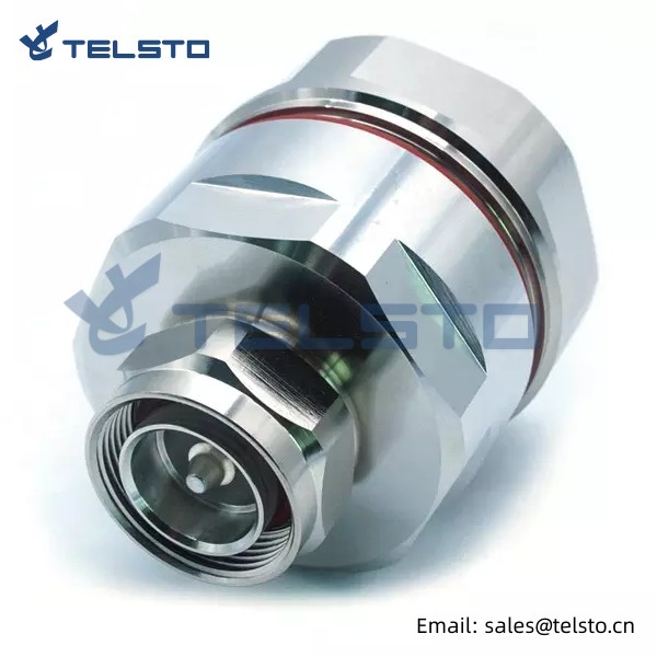
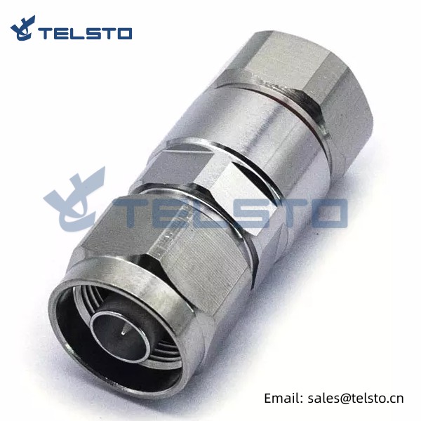
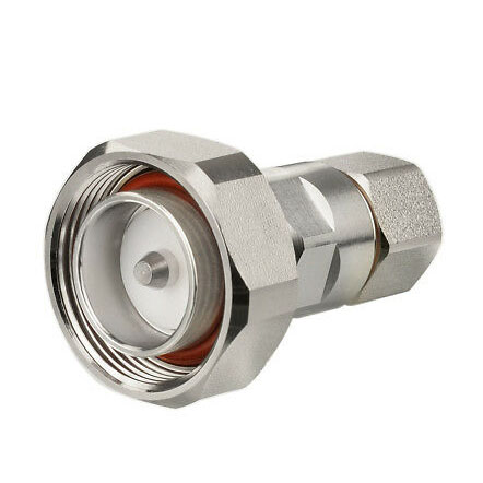
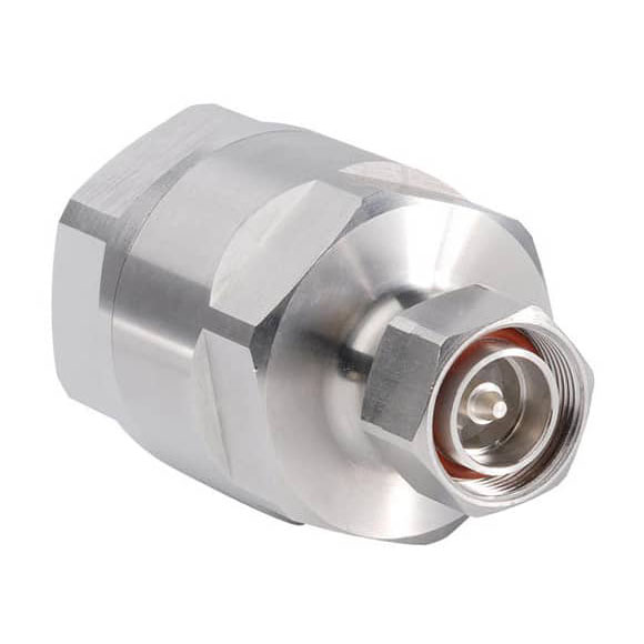
4.3/10 male to N female Connector
Telsto RF offers a full range of 4.3-10 connectors and adapters, which are engineered for the wireless market and are ideal for applications requiring low passive inter modulation, or PIM.
4.3-10 connectors offer the same, robust design as 7/16 connectors but are smaller and up to 40% lighter, allowing for much more dense, lighter weight applications. These designs are IP-67 compliant to protect against dust and water ingress for outdoor applications, and provide excellent VSWR performance up to 6.0 GHz. Separate electrical and mechanical components yield very stable PIM performance regardless of coupling torque, allowing for easier installation. Silver plated contacts and White Bronze plated bodies offer a high-degree of conductivity, corrosion resistance, and durability.
Features and Benefits
100% PIM tested
50 Ohm nominal impedance
Ideal for applications requiring low PIM and low attenuation
IP-67 compliant
Applications
Distributed Antenna Systems (DAS)
Base Stations
Wireless Infrastructure
Related
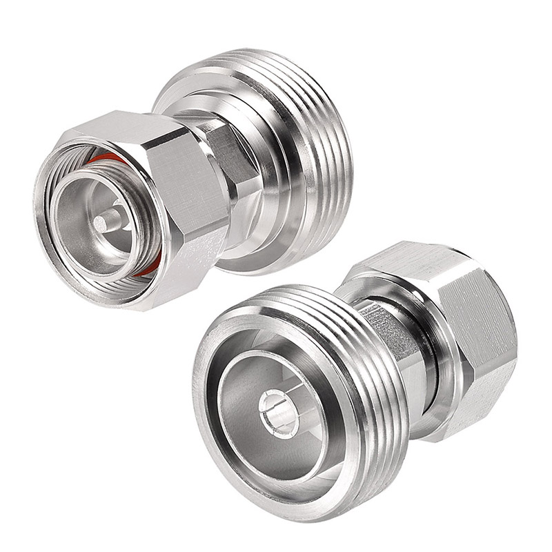
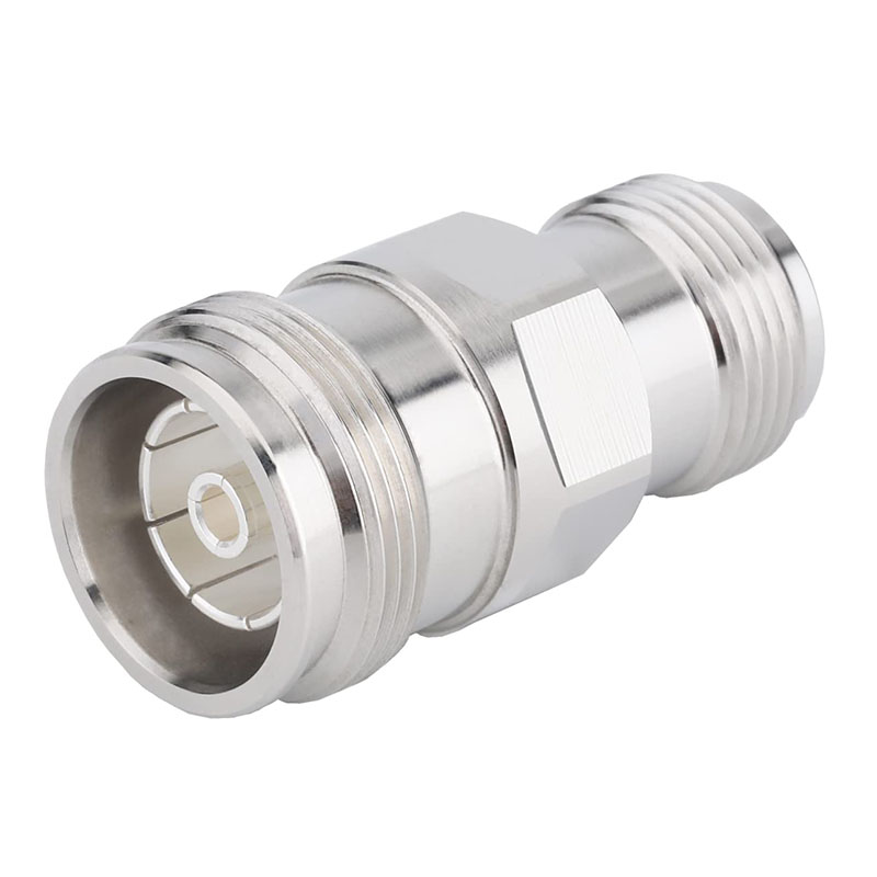
Model: TEL-4310M.NF-AT
Description
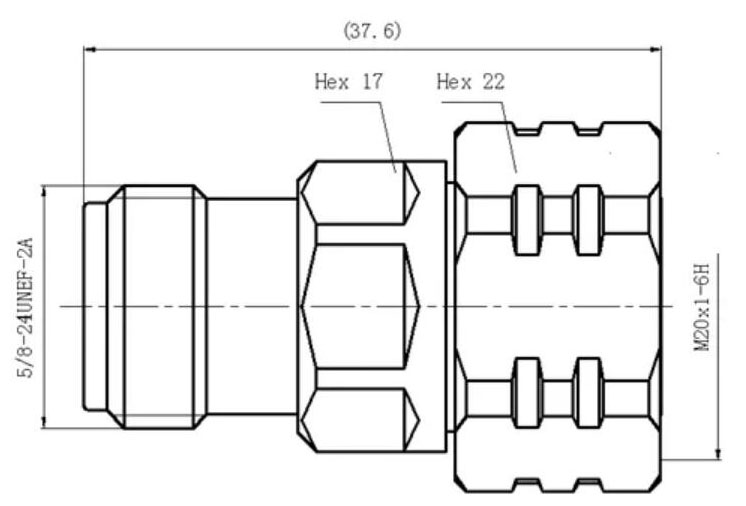
4.3-10 Male to N Female Adapter
| Material and Plating | |
| Center contact | Brass / Silver Plating |
| Insulator | PTFE |
| Body & Outer Conductor | Brass / alloy plated with tri-alloy |
| Gasket | Silicon Rubber |
| Electrical Characteristics | |
| Characteristics Impedance | 50 Ohm |
| Frequency Range | DC~3 GHz |
| Insulation Resistance | ≥5000MΩ |
| Dielectric Strength | ≥2500 V rms |
| Center contact resistance | ≤1.5 mΩ |
| Outer contact resistance | ≤1.0 mΩ |
| Insertion Loss | ≤0.1dB@3GHz |
| VSWR | ≤1.1@DC-3.0GHz |
| Temperature range | -40~85℃ |
| Waterproof | IP67 |
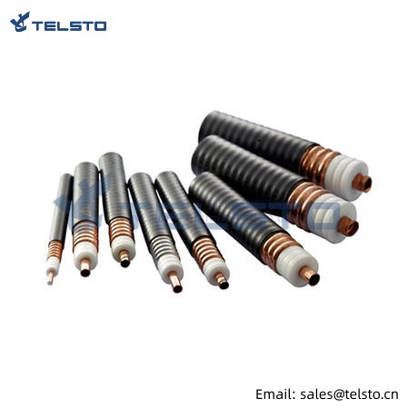
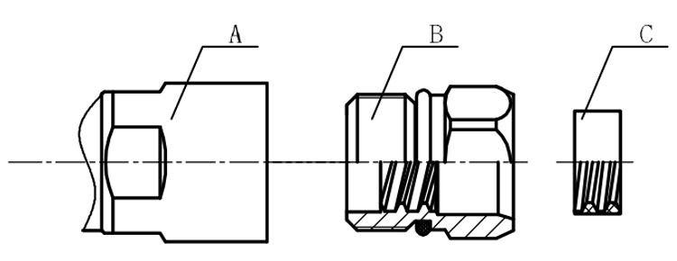
Installation Instructions of N or 7 / 16 or 4310 1 / 2″ super flexible cable
Structure of connector: ( Fig1 )
A. front nut
B. back nut
C. gasket
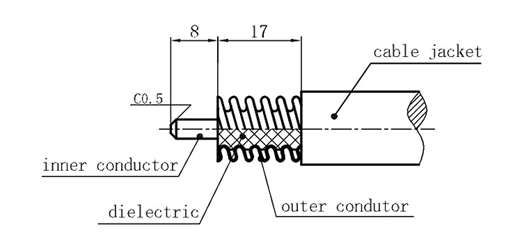
Stripping dimensions is as shown by diagram ( Fig2 ), attention should be paid while stripping:
1. The end surface of inner conductor should be chamfered.
2. Remove impurities such as copper scale and burr on the end surface of the cable.
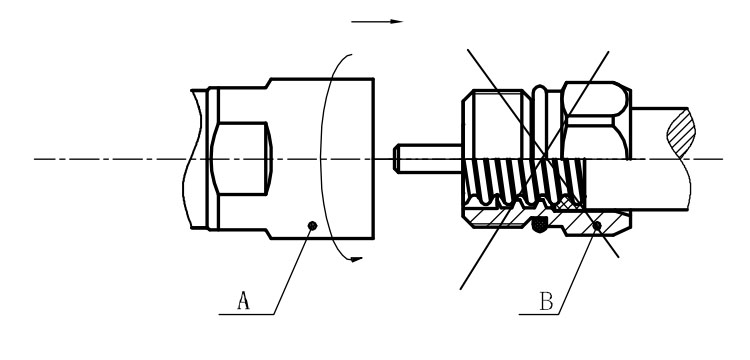
Assembling the sealing part: Screw the sealing part in along the outer conductor of the cable as shown by the diagram ( Fig3).
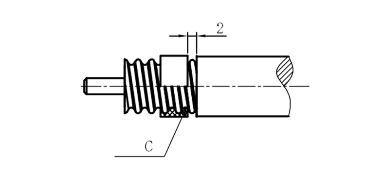
Assembling the back nut (Fig3).
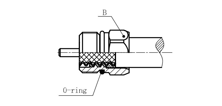
Combine the front and back nut by screwing as shown by diagram ( Figs( 5)
1. Before screwing, smear a layer of lubricating grease on the o-ring.
2. Keep the back nut and the cable motionless, Screw on main shell body on back shell body. Screw down main shell body of back shell body using monkey wrench. Assembling is finished.
