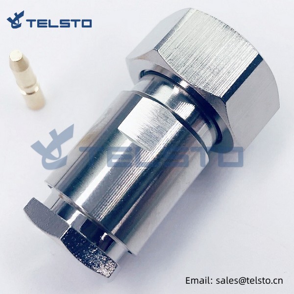
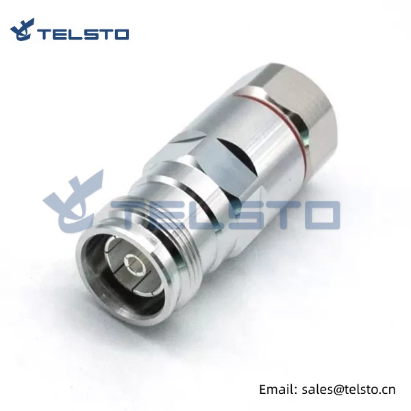
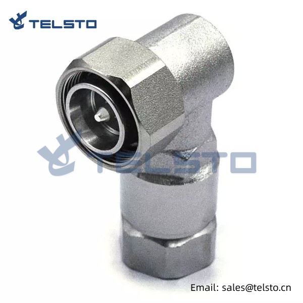
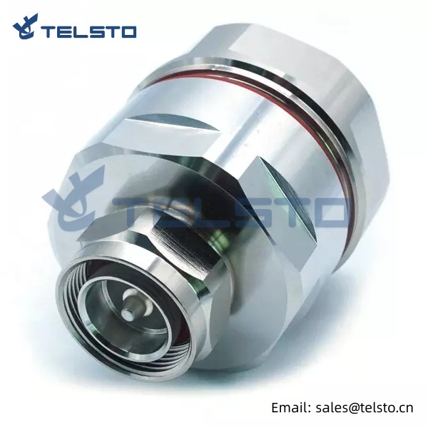
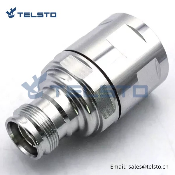
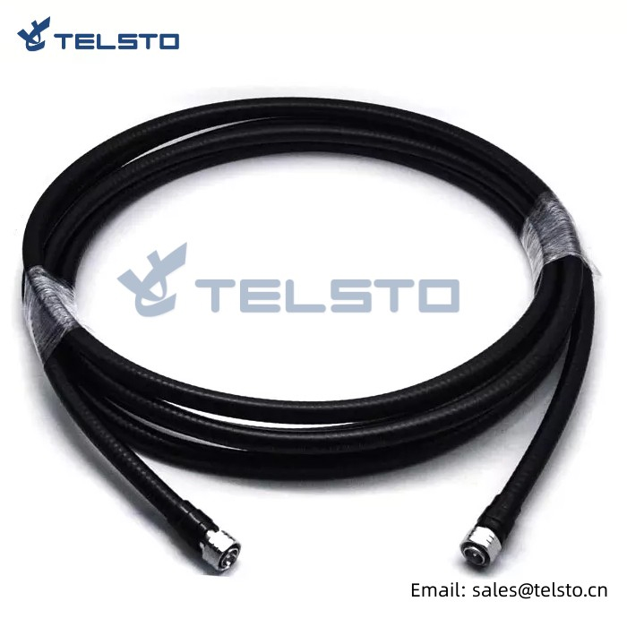
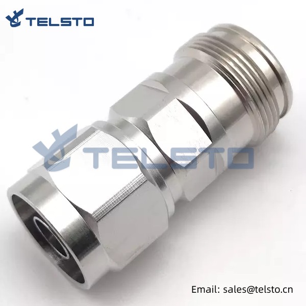
4.3-10 male 4.3/10 mini din for cable lmr400 rg213 crimp type wire connectors with rf coaxial connector lmr-400 adaptor
MINI DIN connectors are used in antenna systems where there are multiple transmitters using the same antenna or where a base station antenna is co-located with a large number of other transmitting antennas.
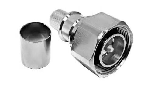
We provide various din connectors for different coaxial cables, such as RG316, RG58, LMR240, LMR400 etc.
We also customize kinds of coaxial cable assembly per request.
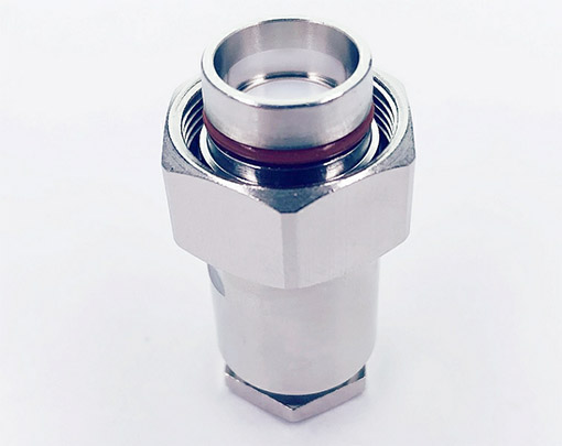
Telsto always believes the philosophy that customer service should be paid high attention which will be value of us.

● Pre-sales service and after-sales service are same important for us. For any of concerns please contact us via the most convenient method, we are available for you 24/7.
● Flexible design, drawing & molding service are available per customer’s application.
● Quality warranty and techincal support are provided.
● Establish the user files and provide lifelong tracking service.
● Strong commercial ability of solving problem.
● Knowledgeable staff to hand all of your account and documents needed.
● Flexible payment methods such as Paypal, Western Union, T/T, L/C, etc.
● Different shipment methods for your choices: DHL, Fedex, UPS, TNT, by sea, by air...
● Our forwarder has many branches overseas, we will choose most efficient shipping line for our client based on FOB terms.
Related
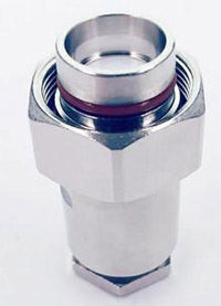
Model: TEL-4310M.LMR400-RFC
Description
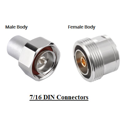
4.3-10 Male connector for LMR400 cable
| Material and Plating | ||
| Material | Plating | |
| Body | Brass | Tri-Alloy |
| Insulator | PTFFE | / |
| Center conductor | Phosphor bronze | Au |
| Electrical | ||
| Characteristics Impedance | 50 Ohm | |
| Frequency Range | DC~6.0 GHz | |
| VSWR | ≤1.20(3000MHZ) | |
| Insertion loss | ≤ 0.15dB | |
| Dielectric Withstanding Voltage | ≥2500V RMS,50Hz,at sea level | |
| Dielectric Resistance | ≥5000MΩ | |
| Center contact resistance | ≤1.0mΩ | |
| Outer contact resistance | ≤0.4mΩ | |
| Temperature range | -40~+85℃ | |
| Mechanical | ||
| Durability | Mating cycles ≥500 | |
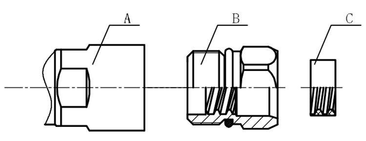
Installation Instructions of N or 7 / 16 or 4310 1 / 2″ super flexible cable
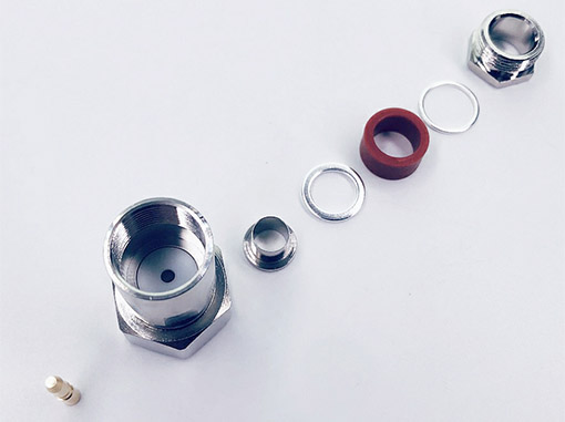
Structure of connector: ( Fig1 )
A. front nut
B. back nut
C. gasket
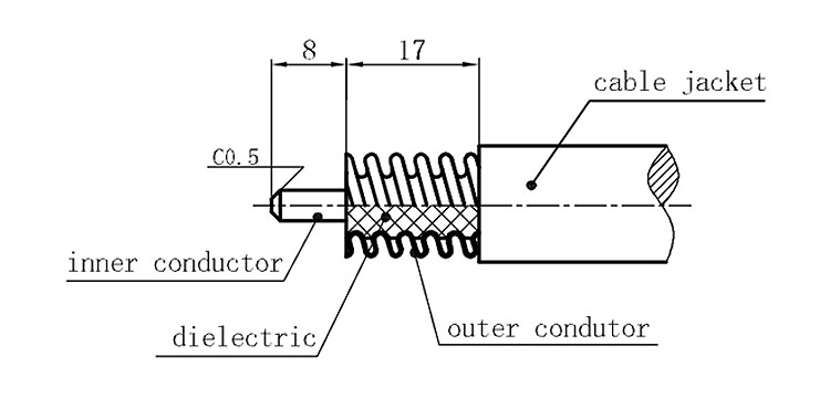
Stripping dimensions is as shown by diagram ( Fig2 ), attention should be paid while stripping:
1. The end surface of inner conductor should be chamfered.
2. Remove impurities such as copper scale and burr on the end surface of the cable.
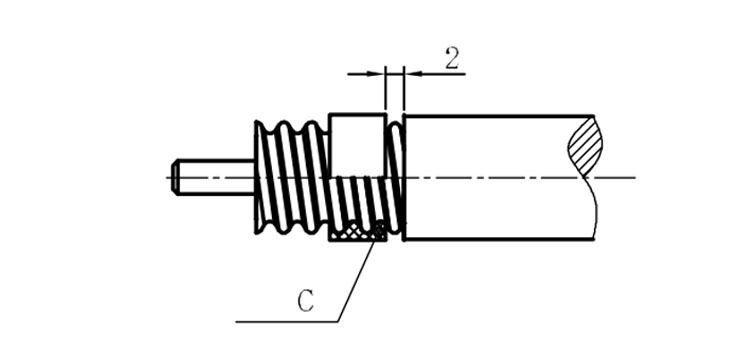
Assembling the sealing part: Screw the sealing part in along the outer conductor of the cable as shown by the diagram ( Fig3).
Assembling the back nut (Fig3).
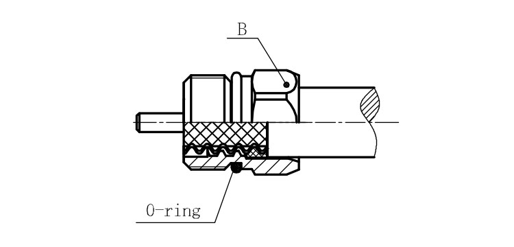
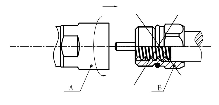
Combine the front and back nut by screwing as shown by diagram ( Figs( 5)
1. Before screwing, smear a layer of lubricating grease on the o-ring.
2. Keep the back nut and the cable motionless, Screw on main shell body on back shell body. Screw down main shell body of back shell body using monkey wrench. Assembling is finished.
